Theoretical and Experimental Investigation for Liquid Film in an Impinging Stream Vortex Chamber
Yang LIU1*, Dong Ma2, Li-hui AN3, Jing-qiu PEI4
1 Associate Professor, Department of Aerospace Propulsion Technology, China.
2 Postgraduate Student, Department of Aerospace Propulsion Technology, China.
3 Associate Professor, Department of Aerospace Propulsion Technology, China.
4 Engineer, Innovation Technology Department, China.
*Corresponding Author
Yang LIU,
Associate Professor, Department of Aerospace Propulsion Technology, China.
Tel: 13720453449
Fax: 02988493406
Email: liuyang802@nwpu.edu.cn
Received: January 24, 2019; Accepted: February 27, 2019; Published: March 01, 2019
Citation: Yang LIU, Dong Ma, Li-hui AN, Jing-qiu PEI. Theoretical and Experimental Investigation for Liquid Film in an Impinging Stream Vortex Chamber. Int J Aeronautics Aerospace Res. 2019;6(2):171-179. doi: dx.doi.org/10.19070/2470-4415-1900020
Copyright: Yang LIU© 2019. This is an open-access article distributed under the terms of the Creative Commons Attribution License, which permits unrestricted use, distribution and reproduction in any medium, provided the original author and source are credited.
Abstract
The paper, based on the special structural features and operation modes of impinging stream vortex engine, starts from the process that two jet flows impact each other and synthetic jet impacts solid wall leading to liquid film, to simplify complex flow process, establishes the calculation model between shape of adherent liquid film and jet conditions, builds the measurement system of adherent liquid film forming when synthetic jet impacts solid wall and finished the experimental verification of liquid film calculation model. The research shows that (1) as impact angle increases, the speed of synthetic jet gradually decreases, the longitudinal area of adherent wall increases and the possibility of liquid film breaking increases; (2) the experimental result of shape of liquid film shows that the calculated result of liquid film analysis model is basically in line with the actual situation with the errors controlled in 10%; (3) the measurement method of thickness of liquid film adopting image subtract operation has a high precision. It is verified that the measurement precision of thickness of system reach 0.01mm, its measurement error is lower than 5% and it can be used to measure the thickness of adherent liquid film inside thrust chamber.
2.Introduction
3.The Calculation Model of Liquid Film Forming Process
3.1 The calculation model of shape of liquid film
3.2 Calculation model of thickness of liquid film
4.Measurement Research and Model Verification of Liquid Film Experiment
4.1 Measuring principle of thickness of liquid film
4.2 Non-contact single-point thickness measurement principle
4.3 Experimental measurement of thickness of liquid film
4.4 Measurement and correction of shape of liquid film Combustor
5.Conclusion
6.Acknowledgments
7.References
Keywords
Liquid Film; Impinging Stream Vortex Engine; Thermal Protection; Impact Angle.
Introduction
Asthemanned space flight project, moon exploration project and other aerospace projects are carried our successively, the power system of liquid rocket, as the main power unit responsible for the flight, posture control, orbital transfer and other tasks of carrier rocket and spacecraft, draws more and more attention, thermal protection and costs increase brought by the improvement of performance of thrust chamber are the difficult problems in the research and development of liquid rocket.
Different from traditional thrust chambers, impinging stream vortex engine, as a kind of new thrust chamber structure, has its likedoublet injectors installed on the side wall of thrust chamber to spout propellant. After atomizing owing to collision, propellants will turn into adherent liquid film on wall to improve thermal protection ability. Meanwhile, its helical motion way is beneficial for the secondary mixing of propellants and extending the resident time of propellants. It has the features of simple structure, good thermal protective performance and short axial length and conforms to the development direction of aerospace science and technology. So, impinging stream vortex engine research is significant in academic and engineering.
In its working process, the shape of adherent rounding liquid film is the key factor limiting its performance. For example, excessively thick or long liquid film will lower its working performance and excessively thin liquid film will influence its thermal protective performance. Currently, the research in the aspect is basically blank, so the forming process of shape of adherent liquid film needs to be studied to provide theoretical basis for the design of ISVE. Currently, the adherent liquid film research of liquid rocket engine is mainly aimed at the thickness and shape of cooling film at the border area of thrust chamber. Japanese Takao Inamura [1, 2] and other researchers carried out massive research on the thickness distribution of liquid film forming when single injector impacts solid surface and cambered surface, put forward a liquid film distribution analytic expression according to mass equation and momentum equation and took advantage of contact measuring method to measure the thickness of liquid film with the measurement result showing that its theoretical and analytical solution is basically in line with the actual situation. Li Hongtao [3] and other researchers with North China Electric Power University took advantage of subtraction algorithm and combined image acquisition instrument to conduct the measurement test of thickness of adherent liquid film, studied the flow and breaking characters of liquid film in free state and obtained the relational expression between the breaking of liquid film outside pipe and fluid Reynold number by fitting experimental data. But owing to the special work mode of impinging stream vortex engine, its forming process of liquid film involves impinging of two injectors, synthetic jet, collision with solid wall and other physical processes, so unlike impinging jet calculation model and the model of jet hitting solid wall need to be considered comprehensively before establishing the shape analysis model of adherent liquid film.
Figure 1. Sketch map of specific structure of ISVE.
Figure 2. Sketch map of structure of flow field of impinging stream vortex engine.
From the above, domestic and foreign scholars have carried out massive fruitful work on the forming and heat transfer performance of adherent liquid film, but owing to the particularity of structure and work mode of impinging stream vortex engine, the research on the forming process model of adherent liquid film is still insufficient, so carrying out adherent impinging liquid film research is essential for no matter improving the design level of impinging stream vortex engine or deepening the learning of formation mechanism of liquid film.
The Calculation Model of Liquid Film Forming Process
In the work process, two jet flows are ejected from like-doublet injector and hit each other leading to impinging liquid film. Under different injecting angles and speeds, the shapes of liquid film are obviously different [4]. Some impinging liquid film continues to develop into liquid filament and liquid drop and the impinging liquid film near the surface of wall hits the surface of inner wall leading to adherent liquid film. The process involves the collusion between two jet flows, synthetic jet, collusion with solid wall and other physical processes.
According to the forming process of liquid film, the principle of calculation model of liquid film is considered as that the unlikeimpinging calculation model of two jet flows is used to obtain the motion parameters of synthetic jet, especially the shape, thickness and speed of liquid film, to determine the contact area of synthetic jet and wall of thrust chamber. However, the calculation model of impinging flow hitting solid wall is used to obtain the shape of adherent liquid film. In order to facilitate analysis and modeling, the paper makes the following assumption on carbonized layer:
(1) The influence of gravity is ignored
(2) Fluid flow is incompressible steady flow
(3) Liquid column impinging curved surface is simplified as a slope
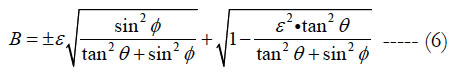
According to Hasson model [4, 5], the commonest model in the research on the research of shape of impinging liquid film of likedoublet injector, mass conversation and momentum conversation of jet flow and liquid film are used to obtain:
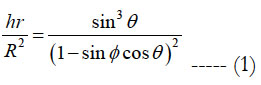
According to the relational expression, the relation between hr/R2 and Φ angle value when two jet flows are at the given impact angle can be obtained. According to the relation, the thickness of impinging liquid film of two jet flows before hitting the wall of engine can be obtained to provide basis for the further research.
Fluid fuel runs around surface of wall. Its speed gradually decreases. And when its speed reaches the critical value, flow speed drops suddenly, some kinetic energies are consumed by turbulence and some kinetic energies transform into potential energy and the thickness of liquid film increases suddenly, which is called hydraulic jump. It is generally considered [6, 7] that when hydraulic jump happens, liquid film is unstable and the thickness is too large and nonuniform, so the paper regards hydraulic jump position as the border of stable liquid film to judge the shape and area of liquid film.
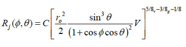
According to reference [7], the distribution of liquid film caused by jet flows hitting solid wall is:
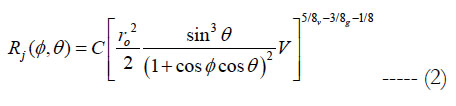
The above model is used to calculate the position of hydraulic jump position of liquid film. The model is deduced from single jet flow, so it needs to be corrected: speed V is calculated according to the synthesis speed of momentum; the thickness of synthetic flow caused by the impact of two like-doublet jet flows is obtained according to Hasson model. And radius r0 in (2) equation is deduced according to the relation between the contact area between synthetic flow and surface of wall and impinging angle θ.
The further analysis tests, measures and verifies the calculation model of liquid film with water as medium, so working condition of calculation is in line with setting of experiment. It is assumed that the flow mass rate of two jet flows is 200g/s, the two jet flows are injected into the inner wall of cylindrical shell, the diameter of nozzle is 4mm, the inner diameter of shell is 180mm and the included angles of jet flows are respectively 30°, 45° and 60°. The shape of liquid film caused by the impact of like-doublet injectors under three working conditions is calculated with the results shown in Figure 4. The calculation shows that when the diameter of jet exit is determined, the distribution of shape of liquid film produced by like-doublet jet before liquid film breaks is related to the relative position of impact point. According to the relative positions of impact points and thrust chamber, calculation results are used to obtain the thickness of liquid film at the contact position of liquid film and surface of wall to obtain the contract area of impinging liquid film and surface of wall.
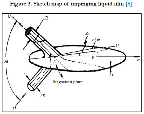
Figure 3. Sketch map of impinging liquid film [5].
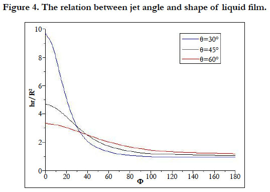

Figure 4. The relation between jet angle and shape of liquid film.
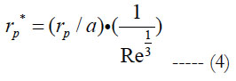
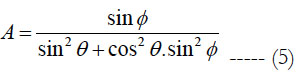
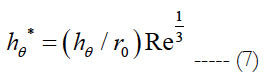
The thickness of liquid film is calculated by referring to reference [8, 9]. It is assumed that the flow is two-dimensional flow, liquid film runs on the surface of wall, the influences of gravity is ignored and the dimensionless thickness h of impinging liquid film conforms to:
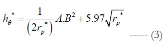
In the equation:
The relation between thickness and dimensionless value is:
According to the above equations, the thickness of liquid film is decided jointly by the synthesis speed of synthetic jet, equivalent diameter and impact angle. When the flow is fixed, speed and equivalent diameter are both decided by the diameter of injector and impact angle, so the distribution of thickness of liquid film can be decided by determining the diameter of injector and impact angle.
After substituting the calculation results of equation (1) into equation (3) according to the calculation model of shape of liquid film, the distribution of thickness of liquid film under three working conditions is shown in Figure 5.

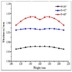
Figure 5. Comparison of thickness of impinging adherent liquid film under three conditions.
Measurement Research and Model Verification of Liquid Film Experiment
In order to verify and analyze the calculation model of liquid film, the paper establishes liquid film measurement system which combines high-speed photography and thickness measurement in measurement; the relation between gray scale difference needed by thickness of liquid film and thickness will be measured and calibrated through micrometer. Meanwhile, micrometer is used to measure single-point liquid film to verify the correctness of highspeed photography; high-speed photography will be used to observe the shape of liquid film to determine the area of liquid film, stagnation position of liquid film and distribution of thickness.
The structure of contact single-point thickness measurement system is shown in Figure 6 and it mainly consists of jet injector, liquid supply system, pressure sensor, multimeter, micrometer depth gauge, surface of wall measurement, catch box and piping system. Its principle is that multimeter, micrometer, wires and liquid film constitute a loop; when micrometer doesn’t touch the surface of liquid film, the loop has an open circuit and multimeter shows that resistance is infinitely great; when micrometer touches the surface of liquid film, the loop is connected, multimeter display a reading of resistance and the reading of micrometer should be recorded; when micrometer touches the surface of shell, the loop has a short circuit, multimeter displays the resistance is 0, the thickness of liquid film is obtained by deducting the previous recorded reading from the reading on micrometer. When micrometer is used to measure thickness, high-speed photography is used to collect the images of liquid film in order to the gray level at measurement points. The method has a simple principle and a relatively high measurement accuracy but can only measure the thickness of single-point liquid film,, so it is used to calibrate the corresponding relation between gray scale difference and thickness and verify and supplement further non-contact measurement method. In order to ensure the precision of measurement, it should be ensured that the probe of micrometer measures along the normal direction of tangent line of movement of the measured liquid film, so the probe of micrometer should rotate surrounding the center of shell and be vertical to the axis of shell. The plan can ensure that micrometer measures the normal thickness of liquid film at any position.
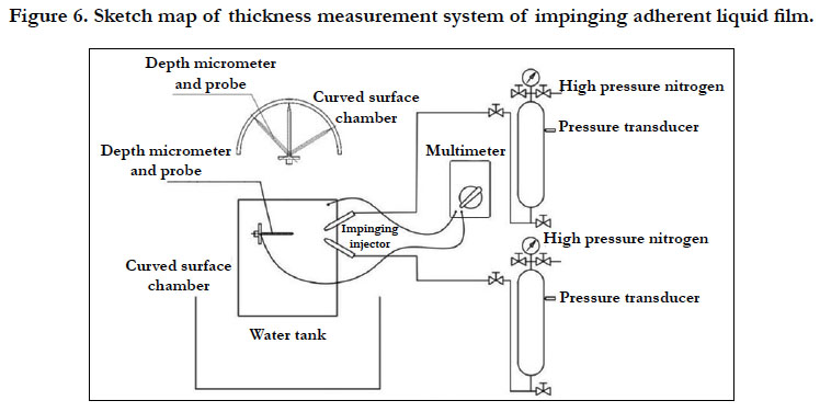
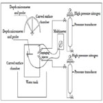
Figure 6. Sketch map of thickness measurement system of impinging adherent liquid film.
The paper takes advantage of image processing technology to process image of liquid film and the background image at the same position as 0-255 gray scale images, conducts filtering, noise reduction and gray scale conversion of the two same images and takes advantage of substractuion algorithm to reduce the gray value of the corresponding pixels of two images to eliminate the interference of gray scale of background of images in order to finish the identification of measurement targets. In test, highspeed camera and background support should be fixed at a position and the same light source should be adopted to eliminate the interference of different light sources with measurement. After eliminating the above influencing factors, the part of collected image covered by liquid film changes, so subtraction algorithm can be adopted to measure the changes of the corresponding gray values of thickness of liquid film. Other than micrometer measurement system, single-point measurement method can be combined to obtain the relation between gray value and thickness, then the distribution of thickness of liquid film can be obtained through the corresponding relation.
Experimental working conditions are in line with calculated working conditions: two jet flows are injected along the surface of inner wall of cylindrical shell, at the flow mass rate of 200g/s and in the tangent direction with the diameter of jet of 4mm, inner diameter of shell of 180mm and the included angles of jet flows of 30°, 45° and 60°. Taking 30° impact angle as an example, because the measured surface is a curved surface, the distribution of thickness of central part of liquid film is measured in order to facilitate measurement.
The gray scale transformation of images of liquid films collected before and after test (Figure 7 and 8) is conducted according to the principle stated above and subtraction algorithm, smoothing filtering, edge detection, gray scale difference, coordinates of thickness conversion and other calculation processes are conducted to obtain the distribution of thickness of liquid film.
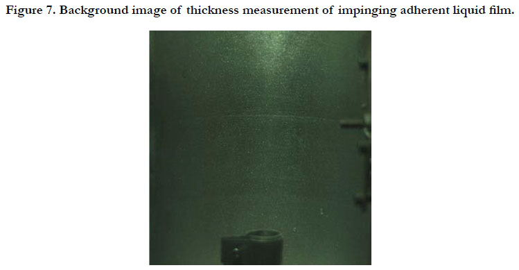
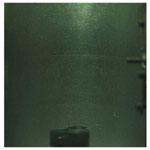
Figure 7. Background image of thickness measurement of impinging adherent liquid film.

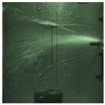
Figure 8. Image of thickness measurement of adherent liquid film under impinging angle 30°.
The obtained gray scale difference is located at the imaginary line in the figure and the relation between gray scale difference and thickness conversion has been obtained through the fitting equation obtained through experimental calibration. Meanwhile, the thickness of liquid film at hydraulic jump position changes suddenly, the thickness can’t be measured with the corresponding relation in calibration and the correctness of fitting formula can’t be ensured, the actual measurement position regards upper and lower hydraulic jump positions as its limit and the measurement of hydraulic jump position is ignored. After the scale conversion of images, the advantages of gray scale difference analyzing and measuring thickness of liquid film is used to select more than 500 gray value points in the image of liquid film within 80mm to obtain the distribution situation of thickness of liquid film at measurement line. As stated above, the measured value at hydraulic jump position is removed when handling measurement results. At the same time, in order to verify the correctness of measurement, multimeter and micrometer are combined to measure and verify the position at the height of 155mm for three times. The results are respectively 0.830mm, 0.899mm and 0.838mm which are approximate to the thickness values obtained non-touch measurement methods with the errors in 5%, so it can be considered that non-touch measurement method leads to accurate measured values and is feasible.
Figure 9 shows the comparison of thickness measured value and calculation results under the impact angle of 30°. According to Figure 9, the distribution of liquid film concentrates in 0.800mm - 0.900mm. The distribution of measured values of thickness of liquid film shows that the thickness of liquid film at the top is slightly higher than that of liquid film at the bottom, which is because upper-end liquid film can’t expand freely on the surface of wall under the functioning of gravity and lower-end liquid film is pulled by gravity leading to the thinning of liquid film. But in general, the distribution range is relatively uniform.
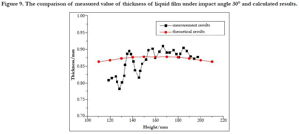
Figure 9. The comparison of measured value of thickness of liquid film under impact angle 30° and calculated results.
In order to compare and analyze the overall distribution of liquid film better, hydraulic jump position in the distribution of liquid film and the plunge caused by the fluctuation of gas and liquid interface are neglected and the smoothing process of filter is conducted to the distribution of thickness of liquid film. Meanwhile, in order to verify the correctness of thickness calculation theory of liquid film in the previous chapter to determine whether it can work as the theoretical guidance for the design of ISVE, the thickness value of measured liquid film and the calculation value under the same working conditions are compared.
It can be found by observing the above figure that the measured value of liquid film at the bottom is different from its calculated, but other calculated values are basically in line with their calculated values. The difference between thickness of lower-end liquid film and calculated value is caused mainly by that the analytical expression of distribution of thickness of liquid film considers the influences of gravity factor, and under the functioning of gravity, the distribution of thickness of liquid film is not uniform, namely the lower end of liquid film is relatively thin and the upper end of liquid film is relatively thick. The whole range of theoretical calculation value is similar to measured value. It can be considered that under 30°, the theoretical value of thickness of liquid film basically conforms to the actually measured value.
In addition, the distribution of liquid film under impact angles 45° and 60° is similar to that under 30°. Owing to the limit of space, those results won’t be provided here. In general, the whole distribution trend of liquid film under the functioning of gravity is slightly different from the theoretical calculation value, but the actual measured value is basically in the range of theoretical calculation value, and it can be considered that the theoretical value of thickness of liquid film basically conforms to the actual measured value and thickness calculation model of liquid film is trustworthy.
High-speed camera is used to shoot liquid film and the area, shape and breaking position of liquid film and other key parameters which can be determined according to the proportional relation between image of liquid film and actual size. Figure 10 provides the corresponding relation between shape and appearance of impinging adherent liquid film and position of shell. The included angle between two injectors is fixed. Two injectors spray on the surface of shell at a fixed included angle and center space of outlet of injector. After impacting each other, two jet flows runs around the wall leading to adherent liquid film. After injector starts to work leading stable liquid film, the images of liquid film are collected. Because the surface of wall of shell is cylindrical surface, the images were collected from many directions in the test in order to ensure the precision of measurement. It can be seen that the image of liquid film is stable, the border line of hydraulic jump area is clear. Liquid film has not broken at the circumferential direction. Owing to the function of gravity, radical direction is not completely laterally symmetric but shifts downward.
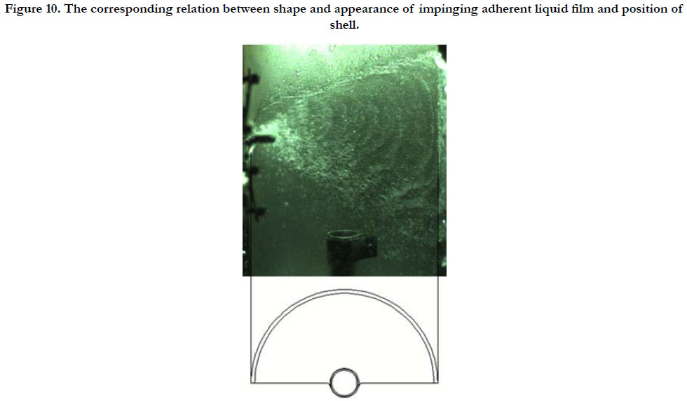
Figure 10. The corresponding relation between shape and appearance of impinging adherent liquid film and position of shell.
Image processing results show that the thickness of hydraulic jump position at the top of liquid film is obviously larger than that at the bottom of liquid film, and the hydraulic jump line of processed tiled adherent liquid film shows that upper-end and lower-end hydraulic jump lines are not symmetric. The calculation model has not considered the function of gravity in order to simplify analysis, so hydraulic jump position needs to be corrected. According to the analysis of forming process of liquid film, the factors which have influences on the shape of liquid film except for gravity are all symmetric laterally and same. Therefore, the correction of liquid film can be finished by analyzing the influences of gravity on hydraulic jump line of liquid film and adding gravity correcting factor.
First, it is assumed that liquid film is stable. In order to simplify the research, the influences brought by the circumferential movement speed are ignored and the running state of liquid film under the functioning of gravity is analyzed. It is assumed that the initial speed of liquid film along the direction of gravity is 0 and liquid film is carrying out laminar motion before hydraulic jump.
One layer of fluid with the thickness of liquid film of y is regarded as fluid unit. As a balance, it can be obtained:
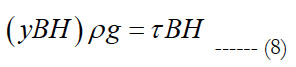
B represents the width of section fluid unit, H represents the height of section flow unit and τ is shear stress.
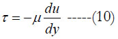
Shear stress is expressed as:
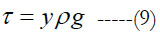
According to Newton law of viscosity:
Linking the above two equations leads to:
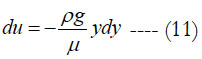
Integrating the above equation leads to:
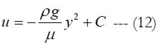
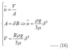
when y = δ, u = 0 and C = (ρg/2μ)δ2, so
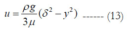
δ is the thickness of liquid film.
In the liquid film with the width of dy, the flow speed is u. According to the balance of flow rate:
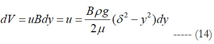
Through integration, the flow rate in unit time is obtained:
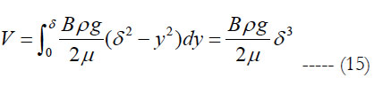
At last, the speed relational expression along vertical surface under the functioning of gravity is obtained by linking the following three equations:
The speed relational expression under the functioning of gravity is obtained through the above analysis. Gravity correction factor of hydraulic jump line of liquid film is obtained by collecting the thickness and running time of liquid film combining test. The corrected hydraulic jump position after substituting hydraulic jump position line of liquid film is shown in Figure 11.

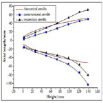
Figure 11. Comparison of measured value and calculated value of shape of liquid film under impact angle 30°.
Owing to the high synthetic speed and the few influences of gravity, the test results under 30° working conditions match with the theoretical calculation values well. When liquid film runs for a period of time, the loss of circumferential speed gradually increases owing to fraction and other factors, lower-end hydraulic jump line gradually deviates from theoretical value owing to the influences of gravity. Because correction factors have not considered the piling of fluid, the situation under other conditions is similar, so there are a few errors between upper-end hydraulic jump line and theoretical value after correction. Though the measured value of shape of liquid film under the functioning of gravity is slightly different from theoretical value, but the errors are acceptable and test results show that the change trend of hydraulic jump position of liquid film is basically in line with theoretical calculation value, so it is considered that the calculation theories of liquid film conforms to the requirements and can provide theoretical basis for the design of adherent liquid film of impinging stream vortex engine.
Conclusion
(1) The paper starts from the injection of propellant by like doublet injectors of impinging stream vertex engine and law of motion of adherent liquid film, determines the influences of jet speed, angle and diameter of injector on shape of liquid film by studying the process that synthetic jet impacts the surface of wall leading to adherent liquid film and obtains the shape analytic expression of adherent liquid film;
(2) High-speed photography is used to build non-contact liquid film measurement system to analyze the area of film and the distribution of hydraulic jump position; gray scale subtraction algorithm is used to measure the thickness of adherent liquid film. Test results show that the distribution of hydraulic jump position and thickness of liquid film basically conforms to the calculation results of theoretical analysis verifying the correctness of analysis and calculation model of liquid film. Meanwhile, contact measurement method is used to verify that the measurement accuracy of non-contact measurement method reaches 0.01mm and the measurement errors are lower than 5%.
(3) The experiment results of liquid film show that the calculation results of liquid film analysis model is basically in line with actual situation and errors are controlled in 10%.
Acknowledgments
This research was supported by the Fundamental Research Funds for the Central Universities (Grant No. 3102016ZB046).
References
- Inamura T, Yanaoka H, Tomoda T. Prediction of mean droplet size of sprays issued from wall impingement injector. AIAA J. 2004 Mar;42(3):614-21.
- Inamura T, Amagasaki S, Yanaoka H. Thickness of liquid film formed by impinging jets on a concave wall. J Propul Power. 2007 May;23(3):612-7.
- Li Hong-tao. The experimental studies to the thickness and the breakdown characteristic of the free falling liquid films based CCD method. Master's Thesis of North China Electric Power Univ. 2005;12.
- Ryan HM, Anderson WE, Pal S, Santoro RJ. Atomization characteristics of impinging liquid jets. J Propul Power. 1995 Jan;11(1):135-45.
- Hasson D, Peck RE. Thickness distribution in a sheet formed by impinging jets. AlChE J. 1964 Sep;10(5):752-4.
- Liu X, Lienhard JH. The hydraulic jump in circular jet impingement and in other thin liquid films. Exp Fluids. 1993 Jul 1;15(2):108-16.
- Kate RP, Das PK, Chakraborty S. Hydraulic jumps due to oblique impingement of circular liquid jets on a flat horizontal surface. J Fluid Mech. 2007 Feb;573:247-63.
- Inamura T, Yanaoka H, Tomoda T. Prediction of mean droplet size of sprays issued from wall impingement injector. AIAA J. 2004 Mar;42(3):614-21.
- Inamura T, Amagasaki S, Yanaoka H. Thickness of liquid film formed by impinging jets on a concave wall. J Propul Power. 2007 May;23(3):612-7.


