Qualification of Composite Structure for Cubesat Picosatellites as a Demonstration for Small Satellite Elements
A. Ampatzoglou1, A.Baltopoulos1, A.Kotzakolios1, V. Kostopoulos1*
1 Applied Mechanics Laboratory, Mechanical Engineering and Aeronautics Department,University of Patras,Rio Campus, 26500, Greece.
*Corresponding Author
V. Kostopoulos,
Applied Mechanics Laboratory,
Mechanical Engineering and Aeronautics Department,
University of Patras, Rio Campus, 26500, Greece.
Tel: +30 2610 969443 /+30 2610969441
Fax: +30 2610)969417
Email: kostopoulos@mech.upatras.gr
Article Type: Research Article
Received: September 02, 2014; Accepted: October 06, 2014; Published: October 07, 2014
Citation: A. Ampatzoglou, A.Baltopoulos, A.Kotzakolios, V. Kostopoulos (2014) Qualification of Composite Structure for Cubesat Picosatellites as a Demonstration for Small Satellite Elements. Int J Aeronautics Aerospace Res. 1(1), 1-10. doi: dx.doi.org/10.19070/2470-4415-140001
Copyright: V. Kostopoulos© 2014 This is an open-access article distributed under the terms of the Creative Commons Attribution License, which permits unrestricted use, distribution and reproduction in any medium, provided the original author and source are credited.
Abstract
The present work describes the design, structural analysis, and qualification by analysis and experimental validation of the 1st Greek cube-satellite developed at the University of Patras (UPSat - University of Patras Satellite). The key innovative approach includes the replacement of the aluminum parts of the primary structure with structural composite components, something that has never been attempted in the past by other mission following such an approach. A Single-Unit (1U) CubeSat structure made entirely of composite materials was designed, analyzed, manufactured and tested. A comparison with the state-of-the-art, commercially available, structure made out of aluminum (CubeSat-kit) already certified for space use also took place. The work was performed under the vision to prove the feasibility of manufacturing and certifying the structure for space use in the near future. Finite element analysis, confirmed by testing of a 1U Cube Sat, is used to examine trade-offs for the materials and layups. Based on these analyses, recommendations are given for a viable design solution. Results have shown that the redesign of the structure using CFRP can offer similar levels of performance in terms of stiffness while reducing mass by approximately 40%.
2.Introduction
3.Simulation Approach
3.1 Design
3.2 Materials
3.3 Launch Environment and Analysis Scenarios
4.Results
4.1 Finite Element Analysis results
5.Experimental Approach
5.1 Manufacturing of composite CubeSat structure
5.2 Modal Survey
6.Conclusions
7.Acknowledgments
8.References
Keywords
CubeSat, Composite Materials, Finite Element Analysis, Modal Survey
Introduction
CubeSats are a type of miniaturized satellites for space research that usually has a volume of one liter (10x10x10 cm), weigh no more than one kilogram and typically use commercial off-theshelf electronics components. The CubeSat project started in 1999 as a joint venture between California Polytechnic State University (CalPoly) and Stanford University’s Space Systems Development Laboratory. These two Institutes published a standard [1] that specifies that major requirements and constrains as well as basic guidelines that each CubeSat must deal with as the design progresses. The purpose of the CubeSat project is to provide a conventional standard for design and development of picosatellites.The project attempts to reduce the cost and development time and to increase the accessibility to space for educational purposes and for this reason the majority of development comes from academia.
As for all space missions, also for CubeSats the structure is one of the main satellite subsystems. In principle, the purpose of the structural subsystem is to provide a simple and robust structure that shall survive launch loads and provide a suitable environment for the operation of all subsystems throughout all phases of the mission’s life. Furthermore the structure mechanically supports all satellite subsystems, attaches the satellite to the launch vehicle, and provides for ordnance-activated separation [2]. Generally, structural design shall aim for simple load paths, simplified interfaces and easy integration.
Design of space structural systems is a delicate balance between mass, stiffness and strength. On the one hand, stiffness is required to ensure the survivability of the instrumentation while on the other hand, by reducing the mass of the structure, it is possible to increase the payload, which improves agility and also reduces the launch cost[3]. The structural and mechanical parts of a satellite generally represent a large percentage of its mass and, therefore, it is important to choose the proper material [4] and structural configurations to minimize mass.
The CubeSat design space is bound by the general constrains and requirements of stiffness and principal eigen-frequency [5]. Additionally, the used materials must be approved for space environment. Moreover, when using composites for space applications, special considerations are always taking place, in order to ensure that the thermal distortions match the respective ones of the PPOD made from Al 7075-T73.
Until now, several CubeSat missions have successfully been launched. A summary of the structural system from previous CubeSat missions is provided in Table 1. It can be seen that the primary choice for structural systems is aluminum alloys with the most common being Al 6061 or Al 7075 and respective grades. Furthermore, in Table 1 are also shown their structural characteristics such as the structural mass, the manufacturing and assembly process each mission followed. An extensive survey of current CubeSats missions and their capabilities is presented can be found in [6] and [7].
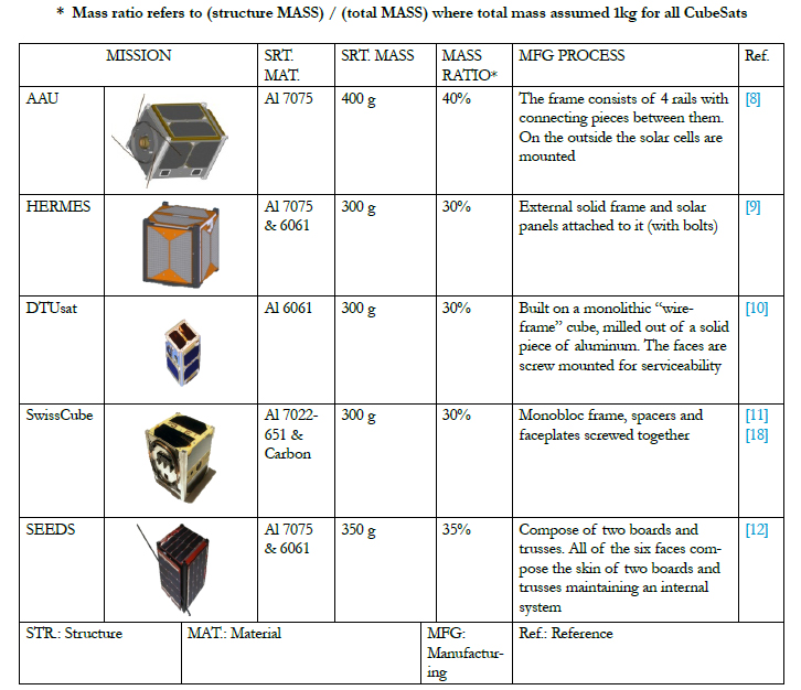
* Mass ratio refers to (structure MASS) / (total MASS) where total mass assumed 1kg for all CubeSats.
Composite materials still represent a very promising class of materials for space applications. Their application has advantages concerning mass and strength, and the required stiffness can be achieved by appropriate choice of fiber types and orientation in a laminate [16]. Furthermore, another remarkable characteristic of composites is the low thermal conductivity that can be beneficial for thermal insulation of low temperature parts [17].
Our work focuses on investigating the use of CFRP in space structural design and the benefits they can offer in smaller structural systems such as those of CubeSats. Even though the use of composites in aerospace applications is steadily increasing in recent years mostly for large structures [13,14], for subsystem parts, such as electronics housing, deployment or deorbiting mechanisms their use is rather limited [15]. To the best of the authors’ knowledge, there has been no in-depth investigation on the use of composites in structural applications for CubeSats or other small satellite elements. Until now, apart from certain missions that composites were used for specific structural components such as the solar panel substrates [18], no team has attempted to use any other material for the structure outside the aforementioned aluminum alloys.
Given the mass, stiffness and strength requirements of the satellite and the interfaces to the separation module, an attempt was made to design and prove the feasibility of manufacturing and qualifying a CubeSat structure made from composites as a paradigm for use in near future missions. The study is formed in two phases; the design and analysis phase and the experimental validation phase. In the design and analysis phase, the system was designed, modeled and analyzed using Finite Element Method (FEM) to derive its modal and shock characteristics. For comparison the reference and commercially available aluminum design was also modeled analyzed. Consequently, the designed composite structural system was manufactured following common industrial practices (pre-preg, Autoclave) and an experimental modal analysis was performed to verify its performance. The agreement with the simulated cases was discussed extensively. Based on both the simulation and experimental study the benefit from using composites in a CubeSat system were quantified.
An iterative design process was followed during this work. The process accounts for the upcoming necessary changes evolving from the interaction between the spacecraft's subsystems. An evaluation in terms of mass and stiffness, of several designs for UPSat structural components took place in previous work [19] and having as baseline the CubeSat-kit design, the best design as it shown in Figure 1a was identified and adopted. Then, using the composite parts the assembled structure of UPS at was created.
The assembly was realized as shown in Figure 1b. In Figure 1c details of how the lateral sides are connected with the top frames are given. Based on the proposed assembly scheme at each edge of the composite CubeSat two connecting bolts have been used. In Figure 1d the typical assembled structure of the reference Cube- Sat-kit is also given [21]. The CubeSat-kit structure is consisting of a monobloc skin and the top and bottom sides are screwed to it using stainless steel bolts.
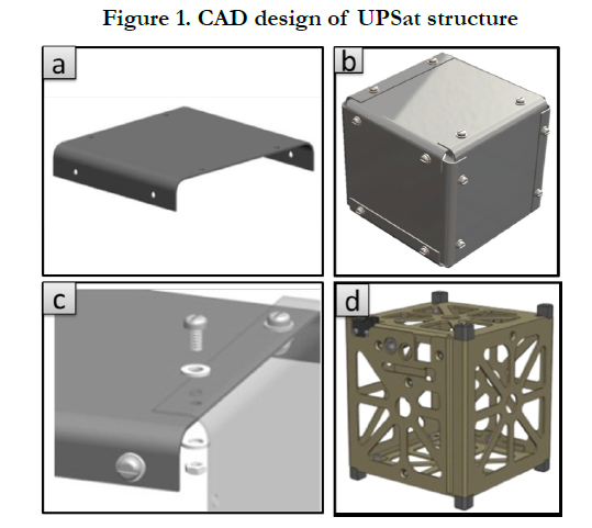
Figure 1. CAD design of UPSat structure
For the Finite Element analysis of the Composite CubeSat shell elements were used since the thickness/length and thickness/ width ratio of the assembled components were small. Shell elements were also used for the analysis of the reference CubeSatkit.
A space approved composite material namely T300-5208 Carbon epoxy unidirectional pre-preg made by Hexcel was selected for the present application. Table 1 shows the full set of properties of the pre-preg material considered.
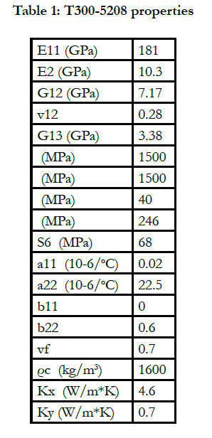

Table 1: T300-5208 properties.
After a trade-off study considering stiffness and mass a quasi-isotropic lay-up was concluded. The resulted lay-up is [0/45/90/-45] S, an eight layers lay-up structure which ends up to a total thickness of 1mm.
For the case of the analysis of the CubeSat-kit an Aluminum structure was considered made out of 7075 Aluminum Alloy (T6) with a total constant thickness of 1mm. The properties of Al 7075 alloy used in the analysis are given in Table 2.
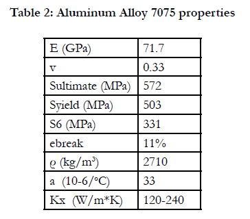
Table 2: Aluminum Alloy 7075 properties.
Finally, for both CubeSat structures the bolts used for the connection of the different components considered to be made by stainless steel and the relevant properties used are given in Table 3.
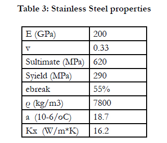
Table 3: Stainless Steel properties.
A typical CubeSat device will be launched on a variety of launching rockets. To qualify for acceptance the CubeSat structure must not fail under certain static loading that will be calculated based on the launching conditions. In addition to static loading, the launching rocket puts out random excitation, with most of the energy of the excitation in the frequency range below 50 Hz. To avoid channeling this energy into violent resonance of the structure, the first frequency of free vibration should be above 50 Hz.
Thus, based on current qualification by analysis procedures [22], two scenarios were considered; a modal analysis and a quasi-static analysis. The specific details of each are given hereafter.
The first step during a dynamic analysis is the determination of natural frequencies (eigen-frequencies) and mode shapes of structure, considering zero damping. The results of this analysis characterize the dynamic behavior of the structure and can show how the structure will respond under dynamic loads [23].
The first step in the modal analysis of a structural system is to determine its natural frequencies given the applied boundary conditions.
The most important modal characteristic of a space structure, like the Cube Sat, is the natural frequency threshold; meaning that the first natural frequency of the structure must be above a specific value, that usually is determined by the launch vehicle. The typical range for such missions is between 50-90Hz, having a lower limit at 50Hz as it was mentioned earlier.
At first a modal analysis of the system under free-free boundary conditions is performed. This is done as an intermediate verification step for the connectivity of developed FE models. Thenthe boundary conditions of the P-POD are applied and another
modal analysis is performed. This part shall reveal the real case scenario of the structural system.
In both cases of Composite CubeSat as well as the reference CubeSat kit one the clamped boundary conditions were assumed as shown in Figure 2c, due to the position of the CubeSats inside the separation module (P-POD), since each CubeSat is restricted by the rails of P-POD.
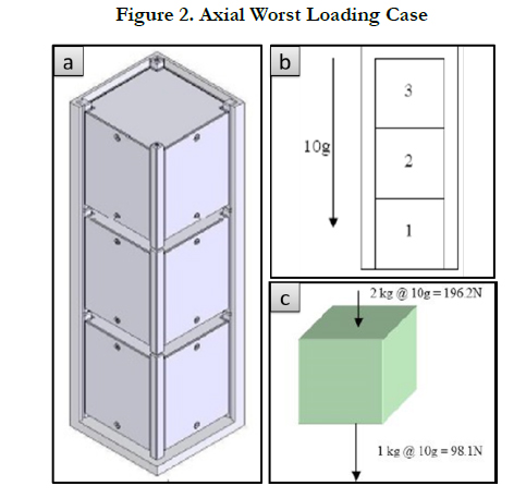
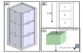
Figure 2. Axial Worst Loading Case.
During the second scenario the extreme quasi-static loading conditions of a CubeSat were identified. These loads apply uniformly all over the primary structure (Inertial Loading) of the CubeSat and include a vibration profile having a frequency content which is significantly below the natural frequencies of the satellite and therefore, will not create magnification of acceleration through the satellite [23].
It is perceived that the worst-case quasi-static loading will be experienced by the satellite during the launch sequence [25]. For the worst case loading consider the arrangement of CubeSats placed within the P-POD shown below (Figure 2).
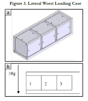
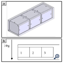
Figure 3. Lateral Worst Loading Case
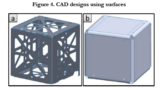
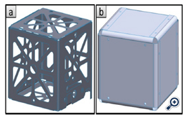
Figure 4. CAD designs using surfaces.
For the worst case quasi-static loading we shall consider the PPOD in a direction parallel to the direction of maximum acceleration during launch. As the deployment system holds three Cube- Sats, the worst case will be experienced by the CubeSat in location 1 of Figure 5. During the launch sequence this CubeSat must maintain structural integrity while supporting not only its own weight but the weight of the two overlying picosatellites.
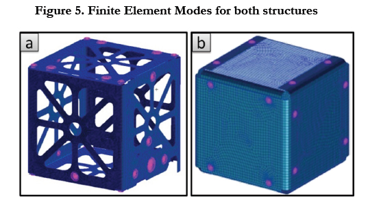
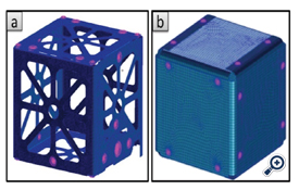
Figure 5. Finite Element Modes for both structures.
Using the CubeSat design specifications the following assumptions can be made regarding the worst case static load of the UPSat:
• The maximum acceleration will be equivalent to 7.5g (Dnepr maximum acceleration)
• The mass of each one of the three satellites is equal to 1kg.
Following the standard procedure for this missions and considering safety factor of 1.25, the maximum acceleration reaches the level of 9.375g, and accordingly this value can be rounded to 10g. The above assumptions were taken from already available CubeSat mission[25] because UPSat is not ready for a flight sothere were not any launcher specifications available. The UPSat will need to be able to tolerate a loading equivalent to an axial force of 196.2N with an acceleration of 10g. This will be known as the worst case axial loading condition.
Now consider a case when the P-POD is aligned in a direction perpendicular to the direction of maximum acceleration. This is shown schematically in Figure 3. In this case all three satellites will experience the same loading condition irrelevant of their location within the P-POD. Assume that the P-POD does not transfer any forces into the CubeSats. Then the CubeSats will only be required to support their self-weight in a 10g gravity field. This will be known as the worst case lateral loading condition[25].
During the launch phase, the CubeSat will ride within the P-PODs devices packaged together and attached on the spacecraft as secondary payload. This configuration represents a low risk to primary payload or other secondary payloads of the spacecraft. Thus there is no specific design for the attachment of the CubeSats to P-PODs and the loads are carried out by the geometrical edges of the CubeSats and flow from the P-PODs package into some sort of adapter, to the spacecraft and finally into the payload attach fitting. The strategy will be to find a set of boundary conditions which favor higher natural frequencies but are mechanically reasonable. This problem is examined in more detail in the discussion of the finite element model.
The designs of both the composite CubeSat as well as the reference one structures were followed the configuration given in Figure 2. Both CAD designs were inserted in MSC PATRAN Preprocessor and the meshing strategy applied. Shell elements (QUAD4 that defines isoparametric membrane bending quadrilateral plate elements with rotational degrees of freedom normal to the plate) were used for the discretization step following the Paver mesher methodology. The concluded Finite Elements Models are shown in Figure 3.
Figure 6 shows three different details of the meshed UPSat structure concerning the meshing (6a) the side’s bolted connection (6b) and the boundaries conditions (6c).
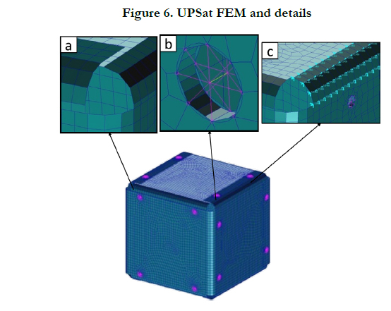
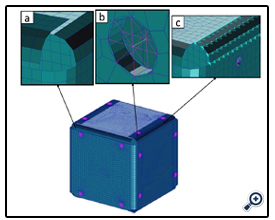
Figure 6. UPSat FEM and details.
The bolts were modeled in all the cases using beam elements (RBE3 Interpolation Element, the interpolation elements allow you to model the motion of one or more grid points as a function of the motion of the other points) offering Multi Point Constrains (MPCs)[20]. For these elements stainless steel properties of were used assigned in all cases of analysis. Concerning the placement of the bolt connection, in the case of CubeSat-kit the instructions as described in the CubeSat kit Documentation [21] were followed. Regarding the number and the placement of the bolts in the case of Composite structure, after an optimization step dealing also with the manufacturing and the assembly of the composite components, 24 bolts were used, 4 per cube side area, along the edges of the structure, as shown on Figure 5b. Again clamped boundary conditions at the 4 lower edges of the system were considered (Figure 6c).
T300/epoxy CFRP material was used for the Composite Cube- Sat with a quasi-isotropic lay-up and UD layer properties given in Table 1. For the CubeSat kit reference structure, aluminum alloy 7075 was considered, with properties presented in Table 2, and finally for the bolts used in both cases stainless steel was used with properties shown in Table 3.
Prior of any analysis, a connectivity check of the model was performed, and after that a detail convergence study of the developed model was implemented. The final mesh used for the rest of the analysis fulfills both the above mentioned checks.
Based on the selected materials and the connecting bolts of both the composite CubeSat as well as the CubeSat kit reference structure made out of aluminum, the masses of the structures were calculated. It was found that reference aluminum structure has a mass of 162 grams, while the composite one has a total mass of 107 grams. This means that the composite structure, despite the fact that no cuts have been made yet, is 35% lighter than the aluminum one.
Tables 4 and 5 present the first 4 eigen-frequencies together with the corresponding eigen-shapes for the reference CubeSat kit structure as well as for the composite CubeSat respectively.
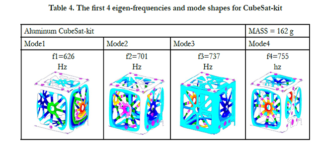
Table 4. The first 4 eigen-frequencies and mode shapes for CubeSat-kit.
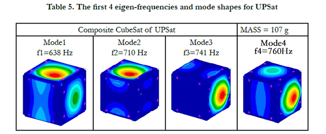
Table 5. The first 4 eigen-frequencies and mode shapes for UPSat.
As it is shown, the composite CubeSat results to slightly lower first eigen-frequency, something that is directly related to the assembly of the composite panels that form the CubeSat. This is concluded, although no cut-outs have been imposed in the composite structure.
Ideally, a more sophisticated connection of the composite panels, that secures full contact along the connection edges may posh the first eigen-frequency to higher value.
As a general remark it must be mentioned that the resulted eigenfrequency values are quite high, but at the level of the present analysis no internal components such as electronic boards, power units, sensors and cameras, were introduced to the structure. Whenever these components will be added, a significant reduction of the natural frequencies is expected.
However, for the needs of comparative evaluation between the reference CubeSat kit structure and the composite one the concluded results provide a solid background for comparison. At this stage, a preliminary modal analysis of the composite frame, using lumped masses for the electronic stacks, demonstrated this reduction but still the 1st natural frequency remained highly above the lower limit of 90Hz (close to 140Hz).
Following the modal analysis, quasi-static analysis was perform at the previously identified maximum loading conditions, both in the axial as well as in the lateral direction. These loads were 30g compression in the axial direction and 10g compression in the lateral direction under clamped boundary conditions, as it was earlier discussed.
Table 6 summarizes the results of the quasi-static analysis performed for the two loading cases, both for the aluminum alloy reference CubeSat kit as well as for the composite CubeSat. For aluminum structure Von Misses stresses have been calculated, while in the case of composite structure the maximum stresses have been used. In both cases maximum displacements are also reported in Table 6. As it is evident from the results reported in Table 6 all maximum stresses and displacements for both quasistatic loading cases and both structures are extremely low, considering the strength of both materials.
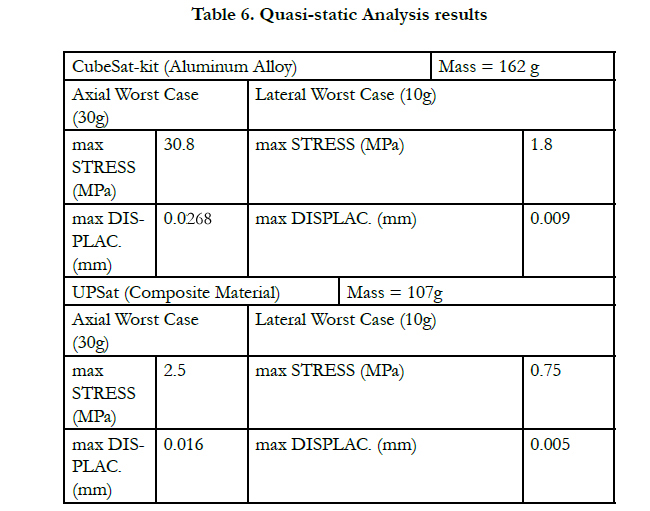
Table 6. Quasi-static Analysis results.
This is expected, since both structures are designed on the basis of a stiffness driven approach, in order to push eigen-frequencies to higher values, as the design criteria request.
Figure 7 presents the stress (a) and the displacements (b) distributions for both CubeSat structures in the case of extreme axial loading of 30g.
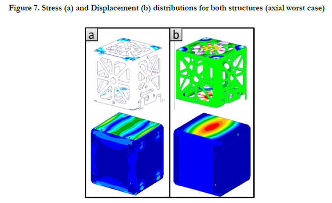
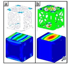
Figure 7. Stress (a) and Displacement (b) distributions for both structures (axial worst case).
The stress distributions show a maximum loading along the edges and around the bolts for both CubeSat structures, while in the case of displacement distributions the maximum displacement appears at the mid points of the top and the lower surfaces of the structures, something that was expected since the inertial load of 30g was applied along the Y-axis.
For the manufacturing process, the first step was the design and manufacturing of two different aluminum molds as it is shown in Figure 8a.
The reason of using two different molds is that all six structure sides are not the same. The four lateral sides are identical while the top and the bottom are slightly different.
Following the standard layup process and using the quasi-isotropic 8 layers stacking sequence which was described earlier, the composite components of the CubeSat were prepared and place in the Autoclave as it is presented in Figures 8b to 8e. The Autoclave cycle follows the curing cycle of the prepreg material as it is given by the material data sheet (3 hours at 120°C and 5 bar of pressure).
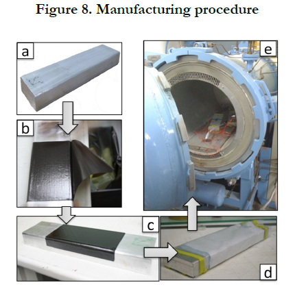
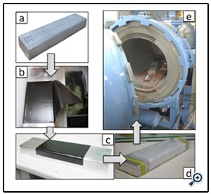
Figure 8. Manufacturing procedure.
Finally after Autoclave, the composite parts removed from the molds, trimmed and drilled according to the assembly design, and the composite CubeSat was assembled using the stainless steel bolts. The mass of the assembled composite structure is 104.5grams. The assembly process is presented in Figures 9a-9c.
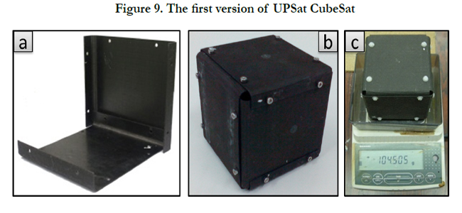
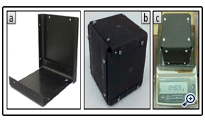
Figure 9. The first version of UPSat CubeSat.
For the purpose of the modal survey for the assembled composite CubeSat, and in order to compare the results of the modal analysis concluded numerically in Section 3.1 against the eigenfrequencies of the real composite structure, it is necessary to simulate in a reliable way the boundary conditions that the P-POD provides to the composite CubeSat structure. Thus, a Test-PODmade of Aluminum and Steel was designed and manufactured as it is shown in Figure 9a. All five plates and connecting bars of the Test-POD structure were made out of aluminum while the base plate, where the CubeSat is fixed was made out of stainless steel for additional rigidity.
Using the Test-POD equipment, the composite structure was clamped at the bottom on the stainless steel plate. Two low mass accelerometers were mounted on the top and the lateral surface of the composite CubeSat, and the system was started to vibrate using as excitation source a Vibrator shown in Figure 9b.
A sweeping vibration approach was used and typical vibration response (amplitude versus time) is given in Figure 10b for the top
surface accelerometer. The FFT analysis of the monitored signals provides the eigen-frequencies related to the specific vibration mode that excites the monitored surface.
Figure 10a shows the analysis of the signal given in Figure 10b, and concludes to the 1st eigen-frequency of the composite Cube- Sat structure, positioned inside the P-POD deployment structure. The first eigen-frequency of the composite CubeSat was found to be at 645 Hz, a value which is extremely closed with the one calculated numerically in Section 3.1, which is 638 Hz. This difference is at the level of 1%, and confirms the validity of the numerical analysis made.
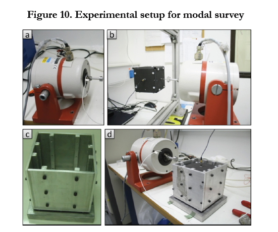
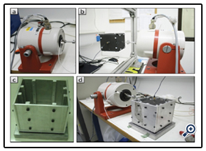
Figure 10. Experimental setup for modal survey.
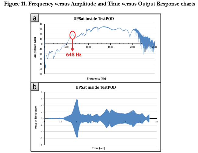
Figure 11. Frequency versus Amplitude and Time versus Output Response charts.
Conclusions
In this study, the use of composite materials was investigated in the design of CubeSat structures. The goal of the study was to design and qualify by analysis and experiment a composite Cube- Sat structure while attempting to quantify the benefits for such a choice.
The first and most important conclusion from the current work is that was realized a successful design and verification by analysis for the first Greek CubeSat. UPSat composite structure offered first frequency higher than the lower limit for space structures that ranges between 70-90Hz. Furthermore comparing the two structures, the Aluminum and the Composite one, an increment of the 1st eigen-frequency was noticed and at the same time the structure mass was decreased close to 35%, even without any cut-outs yet at the Composite structure. This means that using composite materials and after evaluation for the best design and proper lamination, the structure could be more stiff and lighter than the aluminum one.
The results from static analysis, for both cases, showed that all stresses and displacements are very low regarding the strength of both materials. Although the composite materials offered again better results giving smaller values for maximum stress and displacement than the aluminum alloy; something that was quite expectable by the time the Composite structure does not carry any cutting parts yet.
Concerning the preliminary modal survey the results were very promising as they were lined with the FEA ones. Although further testing according to CalPoly and Stanford Universities standards (Random and Sinusoidal vibrations, along with the corresponding FEA analyses) is a crucial step for a more complete and reliable evaluation of the composite CubeSat structure.
Finally, another design is currently considered concerning a Double-Unit structure according to QB50 mission requirements [27]. This structure will be a “hybrid” structure consisting of both Aluminum and Composite Materials components in order to fulfill all the project requirements.
Acknowledgments
The authors would like to thank Dr. Nikolaos Athanasopoulos and Dr. Antonios Vavouliotis for their continuous support and Dipl.-Ing. Aris Kourepis for his support in the manufacturing and testing of the composite structure.
References
- Prof. Jordi Puig-Suari, Prof. Bob Twiggs “CUBESAT: Design Specifications Document, Revision III”, California Polytechnic State University and Stanford University’s Space Systems Development Laboratory, 2005 .
- Wiley J. Larson, James R. Wertz, Space Mission Analysis and Design, 1999
- Sarafin Thimas P, Larson Wiley J. Spacecraft structures and mechanismsfrom concept to launch. Microcosm, Inc; 1995
- ECSS-E-ST-32-08C – Space Engineering-Materials – 31 July 2008
- ECSS-E-ST-32C Rev. 1 – Structural General Requirements – 15 November 2008
- Daniel Selva, David Krejci, “A survey and assessment of the capabilities of CubeSats for Earth observation”, Acta Astronautica 74 (2012) 50–68, 2012
- J. Bouwmeester, J.Guo, “Survey of worldwide pico- and nanosatellite missions, distributions and subsystem technology”, Acta Astronautica 67 (2010) 854-862, 2010
- www.space.aau.dk/cubesat/
- spacegrant.colorado.edu/COSGC_Projects/co3sat/Structures.htm
- dtusat1.dtusat.dtu.dk/
- swisscube.epfl.ch/
- cubesat.aero.cst.nihon-u.ac.jp/english/main_e.html
- J. F. Garibotti, R. J. Reck and A. J. Cwiertny, “Composites for large space structures”, Acta Astronautica Vol. 5, pp. 899-916, 1978
- K.K. Sairajan, P.S. Nair, “Design of low mass dimensionally stable composite base structure for a spacecraft”, Composites: Part B, 2010
- S. Pellegrino, S. Kukathasan, G. Tibert, A. Watt, Small Satellite Deployment Mechanisms, 2000
- H. Bansemir and O. Haider, “Fibre composite structures for space applications— recent and future developments”, Cryogenics 38 (1998) 51–59,Elsevier Science Ltd, 1998
- Timo Brander, Kristof Gantois, Harri Katajisto, Markus Wallin, “CFRP Electronics Housing for a Satellite”, European Conference on Spacecraft Structures, Materials & Mechanical Testing, Noordwijk, The Netherlands, 10-12 May 2005
- ctsgepc7.epfl.ch/09-Structures and configuration/ S3-A-STRU-1-4-Structure_Configuration.pdf
- IAC-10.B4.6B.2, Andreas Ampatzoglou, Athanasios Baltopoulos, Antonios Vavouliotis, Athanasios kotzakolios, Vasillis Kostopoulos “Design and analysis of a full composite structure for the 1st Greek CubeSat by the University of Patras (UPSat)”, 61st International Astronautical Congress, Prague, CZ
- PATRAN/NASTRAN 2005 Documentation
- www.cubesatkit.com
- ECSS-E-ST-32-03C Space Engineering, Structural finite element models
- Matteo Appolloni, Final YGT Report, 2004
- Peter Fortescue, John Stark, Graham Swinerd, Spacecraft Systems Engineering, John Wiley & Sons Ltd, Third Edition, 2003
- Guillaume Roethlisberger, SwissCube structural design and flight system configuration, Master Project, 2007
- Peter Avitabile, Experimental Modal Analysis. A Simple Non-Mathematical Presentation, SOUND AND VIBRATION, January 2001
- QB50_Systems_Requirements_issue_5


