A Review of Flapping Wing MAV Modelling
Mwongera VM
Department of Aerospace Engineering, University of Bristol, UK.
*Corresponding Author
Victor Mwenda Mwongera,
Department of Aerospace Engineering, University of Bristol, UK.
E-mail: victor.mwongera@bristol.ac.uk
Article Type: Research Article
Received: March 19, 2015; Accepted: April 20, 2015; Published: April 29, 2015
Citation: Mwongera VM (2015) A Review of Flapping Wing MAV Modelling. Int J Aeronautics Aerospace Res. 2(2), 27-36. doi: dx.doi.org/10.19070/2470-4415-150004
Copyright: Mwongera VM© 2015 This is an open-access article distributed under the terms of the Creative Commons Attribution License, which permits unrestricted use, distribution and reproduction in any medium, provided the original author and source are credited.
Abstract
Flapping wing flight has been extensively studied in the field of entomology, resulting in observations on the methods of lift production, high manoeuvrability and efficient flight for various natural flyers in differing flow regimes and leading to significant developments in biomimetic theories regarding flapping wing MAVs. In addition, advances in aerodynamic modelling methods have given insight into the un-steady 3-dimensional flow that characterises typical flapping wing flight. Therefore, before attempting to model a flapping wing MAV and analyse its stability, it is beneficial to consider previous studies carried out.
The paper examines hover capable flapping wing flight as presented in previous work. The kinematics and aerodynamics seen in nature and the resulting control methods are explored. The paper additionally looks at existing modelling methods used to study the aerodynamics and overall vehicle behaviour of a hypothetical MAV with an aim to introduce the terminology and specifics of MAV flight, as well as give a brief description of the work done to date in flapping wing modelling. The paper ends by examining methods used to analyse stability of flapping wing models and demonstrates the suitability of bifurcation and continuation methods in determining stability behaviour of flapping wing flight dynamics models.
2.Natural Flyers
2.1 Flapping wing kinematics
2.2 Aerodynamic Mechanisms
2.3 Control of natural Flapping Flight
3.Micro Air Vehicle Modelling
3.1 Aerodynamic models
3.2 Development of dynamic models
3.3 Aeroelastic studies
3.4 Stability studies
4.Conclusion
5.References
Introduction
Micro air vehicles (MAVs) are classified as unmanned aerial vehicles (UAVs) with dimensions not exceeding 15cm and an all-up maximum weight of 100g, as set by the US Defense Advanced Research Project Agency (DARPA). This small size makes them uniquely suitable for operation in areas with limited accessibility due to constraints on space or hostility of the environment. In addition, their small size makes them extremely manoeuvrable and less likely to be detected, and they are likely to be relatively cheap to produce. However, this also means that they are more susceptible to disturbances such as wind gusts. Furthermore, the small size will mean a low payload. These benefits and drawbacks make them ideal for surveillance and monitoring missions, where detectability would be a high priority (such as a hostage situation) or where human access is impossible due to a hazardous environment (detecting levels of a suspected toxic gas leak) and where gusts and turbulence levels are relatively low.
MAVs can be fixed wing, rotary or flapping wing, as exemplified in Figure 1. A lot of research has gone into the development of fixed wing MAVs and some have already been developed, such as the Black Widow [21] and the Trochoid [34]. This is due to the already well established wealth of knowledge of fixed wing vehicles at higher Reynolds numbers and the development of larger UAVs. Fixed wing MAVs also have the advantage of being able to carry higher payloads and have a longer endurance. Their fixed wing lifting surfaces also mean that the stability in response to wind gusts can be tailored to create a relatively stable vehicle. However, these come at a cost of the need to have a long enough strip to land. Also, they are generally incapable of hover and usually have a minimum operating speed and poor collision avoidance properties. This has led to fixed wing MAVs being developed mainly for outdoor surveillance, such as monitoring of streets and alleyways in the urban environment.
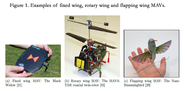
Figure 1. Examples of fixed wing, rotary wing and flapping wing MAVs.
Rotary and flapping wings, however, have the ability to hover and operate at lower speeds. In addition, they can perform perches, thereby saving power whilst still carrying out the mission. Rotary and flapping wings can be made small, with a lower payload and endurance, therefore making them capable of operation within a confined environment and consequently introducing methods of aircraft surveillance that were previously inaccessible. Flapping wing MAVs are more suited to indoor operation than rotary wing MAVs. They fly with less noise, which reduces their detectability. Also, they are less affected by proximity to objects such as walls. Indeed, they can collide with them and still recover flight in a much smaller space, with relatively little damage. Thus, flapping wing MAVs are very desirable as the predominant MAV for surveillance at close quarters.
The flapping wing flight regime has received a lot of attention in the past, such as Weis-Fogh’s studies into flight fitness in hovering insects in [59] and Ellington’s work on hovering flight aerodynamics in [15], leading to theories on the aerodynamics and performance measures of natural flyers. The last two decades have seen a rapid increase in the research focus and subsequent knowledge, leading to developments of flapping wing vehicles such as the Nano Hummingbird and the Mentor demonstration vehicle, shown in Figure 1c and 2 respectively. Additionally, developments in the understanding of the aerodynamics involved in flapping wing flight has led to modelling of the flow field that is close to actual flow, as is presented in [39].
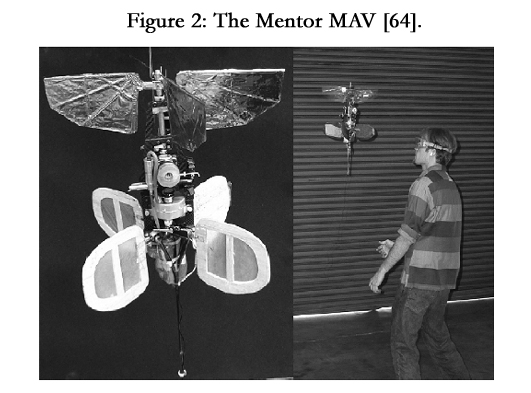
Figure 2. The Mentor MAV.
This increase in knowledge has opened the way for stability studies in flapping flight. The periodic forcing invoked by the flapping kinematics, combined with the large angles of attack, mean that flapping wing flight is highly nonlinear and any trimmed flight solution that contains wing motion is likely to be periodic. Early stability studies involved linearised and decoupled equations of motion and investigated time averaged values of the states, thereby allowing stability analysis of standard state-space equations. Later studies evolved to nonlinear models of the equations of motion and time periodic states. Stability analysis therefore involved location of periodic solutions and analysis using Floquet theory. The stability studies, carried out on models of both natural flyers and MAV designs, usually consider hover or forward flight. These previous investigations, localised to a given set of parameters and a specific design, conclude that hovering flight is inherently openloop unstable, as in [53] and [63]. Therefore, whilst these studies provide stability information on the MAV/flyer studied, there is no research giving generic global stability behaviour for flapping wing MAV design and operation or even information on a particular MAV over a wide operating envelope.
Natural Flyers
The wing movement and flapping method varies considerably in the world of natural fliers. The main characteristic that seems to define the method of flapping is the Reynolds number. Larger flyers, such as birds and bats, which operate in Reynolds numbers of over 50,000, are mainly in the turbulent regime and thus their kinematics reflect this; they flap less and glide more. Insects operate at lower Reynolds numbers that can vary from 100 to 10,000 and corresponds largely to laminar flow. However, this is not a hard and fast rule. There exist some exceptions, like hummingbirds, which operate in a varied Reynolds number from 5,000 to 50,000 [14]. There are also insects which operate within similar Reynolds numbers and yet employ different flight mechanisms for generating lift and thus have dissimilar flight kinematics. However, for most fliers, the flight kinematics described here will vary with Reynolds number. Before examining the different modes of lift and thrust generation in detail, it is necessary to describe the main features that exist in all flight patterns:
Downstroke and upstroke: these are the motions the wing makes whilst flapping. The downstroke consists of the wing moving from its highest positive wing flap angle, through to the most negative wing angle. The upstroke is the opposite of this motion. The combination of a full downstroke and upstroke is a flapping cycle.
Pronation and supination: within natural flyers, the downstroke and upstroke of the wing are accompanied by the wing rotating as it moves. This motion usually begins midway through the upstroke and downstroke, but is mostly present near the end of the stroke. At the end of a downstroke, the wing leading edge is rotated through a large angle such that the incidence angle remains constant through the subsequent upstroke. The top surface ofthe wing then becomes the bottom surface. This process is the supination of the wing. At the end of the upstroke, the wing rotates through a similar angle in the opposite direction, so that the leading edge is still leading and the surfaces have again switched; this is the pronation of the wing. The two motions are indicated in Figure 3.
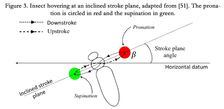
Figure 3. Insect hovering at an inclined stroke plane, adapted from [51]. The pronation is circled in red and the supination in green.
Flapping: this is the rotation of the wing about the longitudinal axis of the body. This is the primary motion of the wing and is found in all natural flyers.
Feathering motion: this motion is the rotation of the wing about the wing’s spanwise axis. Feathering is the primary method of controlling the wing’s angle of attack. It is also how the wing pronates and supinates as it goes through the full flap cycle.
Lagging motion; this is the rotation of the wing about the vertical axis of the body. The lead-lag motion is usually of a smaller magnitude compared to the flapping and feathering values. The combination of the three motions is used to control the magnitude and direction of the overall forces throughout one cycle. The combination of all three leads to the recognized figure-of-eight flapping pattern that can be seen in Figure 3.
Spanning: this motion is the expansion and contraction of the wing, in effect changing the span. It is used to control the force produced during a half stroke. Differential spans can be used to generate a large forward force, or different forces between the wings to create a moment. Spanning is usually seen in larger natural flyers (birds). Shorter wing spans are used for manoeuvring, whilst a larger span is maintained for low energy flight, such as gliding.
Stroke plane: this is the plane in which the periodic wing flapping and feathering motions are confined. The stroke plane can be aligned with the horizontal axis, as shown in Figure 4, or it can be inclined at a certain angle to the horizontal, as shown in Figure 3. A horizontal stroke plane is seen in certain flyers in the hover condition whilst an inclined stroke plane is seen in almost all forward flight cases. Since birds, bats and other large natural flyers do not hover, they always operate with an inclined stroke plane. The only exception is the hummingbird, which does hover (with a horizontal stroke plane).
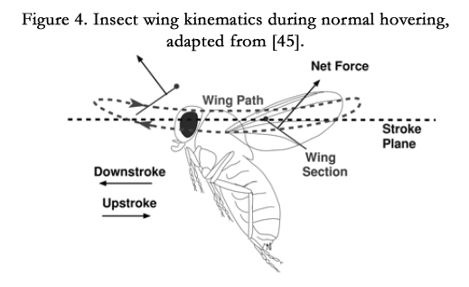
Figure 4. Insect wing kinematics during normal hovering, adapted from [45].
The flapping wing kinematics seem to be divided between larger flyers, such as birds and bats, and smaller flyers, the insects, with the hummingbirds’ flight kinematics falling within the regime of the insect flight. Larger flyers employ flapping, spanning and lagging. Control of these motions is done both at the wing root and along the wing span. In addition, the frequencies of these motions are relatively low. Indeed, these natural flyers take advantage of the wing morphing to generate high lift-coefficient surfaces so as to enable long glide periods.
Insect flight, on the other hand, consists of a wing that does not actively change its shape. The dominant motions are flapping, lagging and feathering. The wings are constantly in motion at high frequencies, in hover and forward flight. It is in this flight regime that a hover-capable MAV falls. Thus, the rest of this literature review will focus on insect flight.
The insect flight flow regime is characterised by low Reynolds numbers and large wing rotations and sub- sequent large angles of attack. In addition to this, the wing is sometimes operating in its own wake, as in the case of hovering. Therefore the flow over the wing tends to be nonlinear, three dimensional and in some cases, unsteady. Natural flyers have developed many mechanisms to enhance lift generation, to extend the range of angle of attack in which the flow remains attached and to also take advantage of the periodic nature of the wing kinematics. This section examines these methods.
Leading edge vortex: The leading edge vortex (LEV) is the main method used by natural flyers, especially at low Reynolds numbers, to maintain attached flow on the wing at large angles of attack. It is dependent on the swirl strength, the rotational rates of the wing motion as well as the Reynolds number. The LEV attaches a bounded vortex core on the upper surface of the wing during the transitional stage (periods of the cycle when the wing is not pronating or supinating), which delays stall and thus allows for high angles of attack. The strength and stability of this vortex varies with the Reynolds number as can be seen in Figure 5 (taken from Shyy et al. [43]).
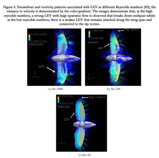
Figure 5. Streamlines and vorticity patterns associated with LEV at different Reynolds numbers [43]; the variance in velocity is demonstrated by the color gradient. The images demonstrate that, at the high reynolds numbers, a strong LEV with large spanwise flow is observed that breaks down midspan whilst at the low reynolds numbers, there is a weaker LEV that remains attached along the wing span and connected to the tip vortex.
The higher Reynolds number shows a stronger vortex core that breaks down before the trailing edge. This bound vortex structure needs a strong axial flow to be able to give it stability. At the other extreme, in the low Reynolds number region, the vortex can be seen to be weaker, but more stable. In fact, it extends all the way to merge with the tip vortex and the trailing edge vortex to form a vortex ring.
The interactions of the LEV within the flow regime is an area of great interest. Dickinson used a mechanical model dynamically scaled to Drosophila (fruit fly) to investigate the effects of the wing rotation on force production and concluded that vortex capture by the wings during wing reversal is a crucial aerodynamic mechanism. Szmelter & Z˙ bikowski [51] examine this phenomenon using Navier-Stokes equations with a hybrid mesh to model the flow around a flapping wing: the numerical integration method captures the unsteady flow around a flapping wing for a given flight condition. The resulting flow calculated shows the presence of the spanwise flow and the vortices around the wing. Wilkins and Knowles [60] investigate the behaviour of a LEV formed by a wing operating at a high angle of attack. The stability of the LEV is investigated for two and three dimensional flows at both high and low Reynolds numbers.
The study of a LEV gives insight into the unsteady flow seen by flapping wings. However, to effectively capture this flow, the model used has to accurately represent the unsteady three dimensional flow present in flapping flight. This is usually done by use of the Navier-Stokes equations to develop the model.
Clap and Fling: The clap and fling technique, as identified by Weis-Fogh [59], is an aerodynamic phenomenon that arises from manipulation of the wing kinematics. It is an effective means of lift enhancement, especially adopted by small flyers in the Reynolds number region of order 10. The motion is as the name suggests: the wings are clapped together then flung apart at the end of each stroke. This results in a bound vortex on each wing edge, which remains attached over the subsequent stroke, thus inducing circulation on the wing, creating a pressure differential and thus encouraging high values of lift. This is shown in Figure 6.
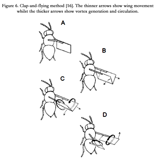
Figure 6. Clap-and-flying method [16]. The thinner arrows show wing movement whilst the thicker arrows show vortex generation and circulation.
Wing rotation: The mechanisms of force production enhancement described so far have affected mostly the translational part of the flapping cycle. However, when at pronation or supination, there is a large contribution from rotation that cannot be ignored. This wing motion produces an added circulation to the flight motion, similar to the added forces seen in a cylinder within a flowing fluid and spinning about an axis perpendicular to the flow: the so called Magnus effect.
The effects of rotation in relation to lift and drag production have been studied and validated by many researchers, including Sane & Dickinson [40], Walker [56] and Hao Wu et al. [61]. The effect of the wing rotating changes the effective velocity at the leading edge, according to the timing of the wing rotation. A wing that begins to rotate before reaching the end of a half-stroke cycle will result in a decreased effective velocity seen by the wing leading edge as the wing rotates; thus there will be an increased resultant force oriented with the wing’s lift force. Similarly, a wing that rotates after the end of a half cycle will have an increased velocity at the leading edge as it rotates, producing a force oriented opposite to the wing’s lift force. More detailed work exists showing the exact effects of wing rotation [10, 11, 40 ,61]. However, the general theory is similar. A wing which rotates in advance of the end of the half cycle will produce a favourable aerodynamic force (as it has a vector in line with the lift force) whilst a wing that rotates lagging the end of the half stroke produces a detrimental aerodynamic force. A symmetrical rotation, where the point of maximum rotation velocity corresponds with the end of the half cycle will experience an intermediate effect. The wing rotation effects are demonstrated in Figure 7.
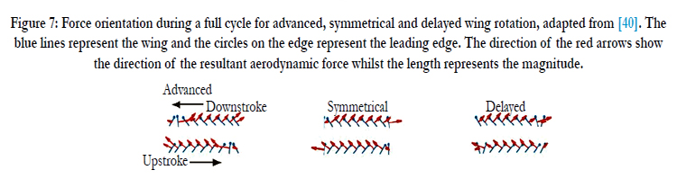
Figure 7: Force orientation during a full cycle for advanced symmetrical and delayed wing rotation, adapted from [40]. The blue lines represent the wing and the circles on the edge represent the leading edge. The direction of the red arrows show the direction of the resultant aerodynamic force whilst the length represents the magnitude.
Wake capture: The periodic motion of the wing means that it is likely to operate within its own wake, especially in the hover case. The wake of the wing contains kinetic and heat energy impacted on it from the wing. As the wing then moves through this wake, it could be possible to recover some of this lost energy, thus utilising less energy in the subsequent stroke. This method is particularly useful in flyers with two pairs of wings, such as dragonflies [51], where the wake of the first wing not only impacts the wing itself but also affects the second wing.
Grodnitsky & Morozov [24] studied tethered insects through dust visualisation to try and observe the vortex and wake formations during a cycle. The studies showed that the flapping flight resulted in a vortex that was shed through the flapping motion. It was also suggested that insects and birds must have some mechanism of extracting energy from this near vortex wake. Birch & Dickinson performed similar experiments in [3] on a robotic flapper to examine the effects of vortices on force production. It was found that the wake influenced the aerodynamic forces near stroke reversal points, where the shed vortices from the previous halfstroke interacted with the wing.
The field of control and stability within the flight regime of insects is a research area that has received a lot of interest. This section therefore examines the mechanisms used in flapping flight control and stability, leading to the determination of what the likely control inputs of a flapping wing MAV would be.
Control of flapping wing flyers has been shown to be similar to the control employed in rotary winged flight [30]. The existence of a stroke plane is similar to the rotor blade plane, and a lot of the control is carried out by orientation of the lift force and thus the stroke plane. However, some differences do exist between the two. As a result, the main aspects involved in control are listed below.
- Stroke plane: This is the main control aspect for most flyers. The stroke plane angle determines the direction of the resultant force vector from a flapping cycle. To achieve hovering, the stroke plane is tilted so that the resultant force is in the opposite direction to the flyer’s weight, much like a rotorcraft. Similarly, forward flight is achieved by tilting the stroke plane to give a thrust vector pointing forwards, thus resulting in a lift and propulsive component. The stroke plane can also be tilted sideways to provide an overall side force and a resultant rolling moment. The combination of the two leads to turns similar to fixed wing aircraft, where the flyer rolls the body and increases the thrust vector to perform a turn. The tilting of the stroke plane is achieved through control of the magnitude of the three rotational wing motions. As an example, increasing the amplitude of the lead-lag motion will result in a tilt of the stroke plane and an increase or decrease in the thrust component.
- Flapping angle: Change in the flapping angle will have a large effect on the aerodynamic forces produced within the cycle. Variation of the flapping angle leads to a change in the resultant forces within one cycle; this can be used to maintain a given trim (such as hover) or generate the forces required for rapid manoeuvres (such as collision avoidance).
- Flapping frequency: An increase in the flapping frequency results in an increase in the resultant force produced. Flapping frequency can be increased equally for both wings or differentially. An equal increase brings about an overall increase in the lift force. This is normally used when sudden large increases in the resultant force are needed, such as in conjunction with the tilting of the stroke plane to maintain altitude or control of the flyer’s altitude in hovering. Differential increase in the flapping frequency results in a rolling moment being produced, with the direction depending on the wing with the greater flapping frequency.
- Feathering angle: This is the largest contributor to the wing angle of attack and can therefore be adapted to change the magnitude and direction of the resultant aerodynamic force and moment; it consequently has direct control on the flyer’s lift and thrust forces. The feathering can be set for symmetric or asymmetric force production within a flapping cycle to suit required flight conditions (hovering or forward flight). Some flyers have been shown to increase the angle of attack to large values therefore leading to a large drag value, which is vectored to produce a large instantaneous force and perform rapid manoeuvres [57]; this can achieve an initially large acceleration from rest over a very small time period, or high turn rates. Differential feathering is also used in conjunction with flapping to produce yawing motion. A pair of wings with different angles of attack but similar flapping motion will result in different lift force components between the wings, creating a large and sudden rolling moment.
Of the methods above, the tilting of the stroke plane is the most commonly used in manoeuvres as it requires low energy and is the most efficient [16]. The disadvantage of this method is that it is dependent on the resultant tilt of the body, and thus the inertial properties of the fuselage [16]. Stroke plane tilt is therefore useful for manoeuvres that do not require an immediate response, such as transition from hover to forward flight, steady turns and climbs. For brisk manoeuvres, natural flyers tend to use other control methods than the changing of the stroke plane. Most of these manoeuvres are for a short period of time, but result in large forces and moments [15]. These manoeuvres, usually confined to within a single cycle, are used especially when reacting to external disturbances in the hover and steady flight. Natural flyers are faced with wind gusts and surface proximity effects such as wall and ground effects. However, most of these exist in the range of low frequencies (approximately 1Hz) and the flapping frequencies of natural flyers are relatively high. Thus, most of the disturbances are quasi-steady and rapid modifications in the flapping and feathering angles and frequencies are more than enough to maintain the desired flight condition [43].
In addition to this, natural flyers use the rapid manoeuvres in the hover condition to maintain a desired flight state. Hovering in flapping flight has been found to be open-loop unstable, from studies of insects such as the desert locust [52-54] and fruit fly [19]. Stabilisation of hovering flight in nature is therefore achieved through feedback control using the rapid manoeuvre methods such as adjusting of the angle of attack and differential flapping between the wings within one cycle.
The investigation into stability to be carried out in the thesis will involve examining the steady state values of flight conditions of a flapping wing MAV. Therefore, the methods of controlling the flight will not involve those restricted to a single cycle; the control methods will involve adjustment of the stroke plane angle to achieve stable trimmed solutions.
Micro Air Vehicle Modelling
The recent development of aerodynamic models and growing interest in the field of flapping wing MAVs has resulted in various methods for modelling such devices and carrying out stability analysis of the periodically forced system. Examination of the available literature reveals that determination of the equations of motion governing the body dynamics of flapping wing flight and representation of the forces and moments within the equations is dependent on the assumptions made and the effects being studied. The literature review has therefore been presented in broad categories in order to highlight the main features of models developed so far.
Aerodynamic models
The area of MAV aerodynamics has generated increased interest over the past years. Many models have been developed to investigate the flow field both qualitatively and quantitatively, from early estimates done by Hoff [26] and Osborne [37], to stated principles by Weis-Fogh [58, 59], to later analysis and proven theories by Ellington [15] and Sane & Dickinson [41]. In addition, the development of computational modelling has led to the development of many aerodynamic representations using a variety of assumptions. Developed models have been listed, categorised and analysed by many others, including Ansari et al. [1], Platzer et al. [39] and Mueller [35]. These aerodynamic model types can be grouped into the classes mentioned below.
Steady state models: As the name suggests, these models assume the flow to be at a steady state. Most of the analysis comes from momentum theory. If the flapping frequency is assumed to be large enough, then the stroke plane containing the flapping wing can be taken as a momentum disc that constantly imparts momentum on the fluid. Thus, the momentum theory of propellers (Rankine-Froude theory) can be used to compute induced velocity at the actuator disc and, from this, thrust and power requirements, as done by Weis-Fogh [58]. The steady state model was enhanced by Ellington [15]: the area of the momentum disc was modified to reflect the dependence of the stroke plane on the flapping angle and stroke plane angle, and was therefore modelled as a partial actuator disc, as shown in Figure 8. Steady state models are useful due to their simplicity. They can be used for quick estimates of minimum power requirements. However, because of the simplification, the power requirements derived from this analysis are considered to be minimum power requirements, and a more detailed analysis is needed to make a better estimate.

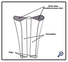
Figure 8: Modi ed actuator disc used in momentum theory calculations, adapted from [15].
Quasi-steady models: Quasi-steady models are based on the quasi-steady assumption: that the instantaneous forces on a wing at a given point in the cycle are the same as those that would be attained by the wing at the same values of angle of attack and induced velocity, if the flow was allowed to fully develop. A quasi-steady model can include not only the states but their derivatives, in an effort to model unsteady effects in a simple way. The quasi-steady model for insect flight was first developed by Osborne [37], who took the values of lift and drag co-efficient to be constant across a half-stoke. Thus, the co-efficients derived are assumed to be the averaged co-efficients through the cycle, determined from considering the force balance in hover and are assumed constant along the span and across the half-strokes. This method, combined with blade element theory, gives the instantaneous aerodynamic forces produced by each aerofoil section. The instantaneous wing forces are therefore attained by integrating the resolved forces along the wing radius and the total force by averaging this over a cycle. This method has the advantage of simplicity and accuracy. The force and moment co-efficients are determined by assuming the flow is fully developed, and therefore the model is assumed steady. The determination of the lift and drag co-efficients can be taken at varied points in the cycle, thus providing a useful method for developing models for analysis that are accurate enough yet not too complex to run time simulations.
Ellington’s work in [15] also examined quasi-steady modelling in flapping wing flight. By considering both the translational and rotational motion, Ellington derived an expression for the lift co-efficient using thin aerofoil theory and the Kutta-Joukowski condition. This lift co-efficient includes a rotational term that is dependent on the angular velocity of the wing (ά), therefore introducing a link between the lift co-efficient and the wing rotation.
Quasi-steady models have had modifications to be able to improve the accuracy. Sane & Dickinson [40] developed the theory of enhanced lift from the rotational motion and produced both empirical data and approximate models. Ansari et al. [1] also modified a blade-element quasi-steady model by coupling it with a Glauert analysis to model the effects of the tip vortices. Ellington [15] suggested a modified induced downwash model, similar to that used in steady state models, as a correction to the velocity derivation in the hover case.
One method of quasi-steady modification that has shown promise is the development of curve fitting quasi-steady aerodynamic equations from current or previous experimental data such as Traub’s work [55] on development of analytical aerodynamic equations and Dickinson’s [11, 41] robofly experimentations and resulting lift and drag expressions. Empirical corrections are advantageous, as they provide a computationally cheap method of aerodynamic modelling and tend to have good agreement with experimental results. However, they are dependent on the range and accuracy of the original empirical data and the additional correction factors.
Unsteady methods: Unsteady models, unlike previously mentioned models, derive the forces and moments produced by examining the resultant unsteady three dimensional flow that develops on a wing. They model the leading edge vortex and the trailing edge vortex, and the effects of these vortices on the flow over the wing. In addition, the wake effects can be taken into account, as the models are time dependent. They are therefore ideal for the examination of the aerodynamic effects that exist within natural flyers. Unsteady models developed in the past have been unsteady panel codes [27], strip theory methods modelling unsteady two dimensional flow [38] or full three dimensional Navier Stokes models [1, 43].
Unsteady models tend to be highly accurate at a cost in computation time. This can be a large disad- vantage, especially if combining the model with others, such as in a full body dynamics model.
Development of dynamic models
Flapping MAV wings are characterised by having multiple degrees of freedom. Depending on what is being examined, the vehicle can therefore be treated in a multibody sense, with a choice of different methods of modelling the same physical movements. In [6, 31], Lasek et. al. derive equations of motion using the Gibbs- Appel equations [2] for control studies. The control of the flapping and lagging motion for each wing is achieved by introducing a control vector to the set of nonlinear equations to attain stabilisation and tracking of the model.
Bolender [4] developed a set of equations using Kane’s system of equations [28] with the aim of creating a generic model that could be used for multiple geometries. The model developed can therefore mimic natural flyers with segmented fuselages that have multiple degrees of freedom (head, thorax and abdomen of insects) or larger flyers that use complex sectioned deformations on the wings in flight (bird wings). The model is used in [42] as a basis for studying implementation of longitudinal control to an MAV. These systems of equations are both extensions of D’Alembert’s Principle, as given in [22, 23]. In [36], Orlowski et al. derived a model using this principle applied to rigid bodies and derived a set of equations that were used in conjunction with time averaged aerodynamic co-efficients to carry out numerical iterations.
Newton-Euler equations have also been used extensively in modelling. Deng et al [9] use this method to derive a set of equations describing the motion of a MAV design, which is then used in [8] to study implementation of control methods using periodic proportional controllers. Similarly, Loh and Cook develop a Newton- Euler based set of equations in [32] that explores attaining stability by changing the inertial properties of the vehicle through a segmented fuselage with multiple degrees of freedom. Sigthorsson et al. [44] developed a Newton-Euler model coupled to curve fitted quasi-periodic aerodynamic equations with an aim of investigating the possibility of providing a 6 degree of freedom flapping wing MAV stability using a 4 degree of freedom controller.
It is therefore apparent that there exist multiple methods of modelling the dynamics of a flapping wing vehicle. The choice of principles to use to derive the set of equations is affected by the method of implemen- tation and purpose of study.
Aeroelastic studies
Most of the models and studies mentioned so far have involved rigid body models. The study of flexible wings in the past has mostly been experimental, with the study of insects and their wing deformations under manoeuvres [58, 59]. Nonlinear wing deformation and the resultant aerodynamic coupling has only recently begun to attract large interest. Gogulapati et al [20] investigated the impact of the inertial and aerodynamic loadings on wing deformations and resulting coupled interactions. The model developed used approximate unsteady aerodynamics and the analysis used an updated Lagrangian method. The study demonstrated favourable aeroelastic coupling in the system.
Su and Cesnik use a simplified version of an aerodynamic model developed in [47] to carry out stability analysis of a tail-sitter flapping MAV design [48] using nonlinear equations in the hover condition. The model developed in [47] is a low order nonlinear elastic model coupled to an unsteady aerodynamic model. In [48], empirically curve-fitted quasi-steady values were used in place of the unsteady aerodynamic model and coupled to nonlinear equations of motion to carry out stability analysis about the hover condition. The stability results and methodology are discussed in the next section.
The various studies presented demonstrate that aeroelastic simulations are indeed possible. However, the nonlinear nature means that the resulting dynamical model will be computationally expensive.
Stability studies
The periodic forcing inherent in flapping wings has meant that, for any operating condition where the wings are in motion, the steady state values are limit cycles. In addition, the complex behaviour exhibited by the system leads to equations that, at a given operating point, are nonlinear and time-periodic (NLTP). Early studies of the stability of flapping wing flyers focused on the hover condition and, using cycle averaged values coupled with linearised equations of motion, attempted to gain a basic understanding of the behaviour. Taylor and Thomas in [54] derived expressions for the motion of a desert locust in hover by using linearised decoupled equations of motion, such as described in [7], and obtained the mass distribution and stability derivatives from experimental measurements. They identified three longitudinal modes: one stable subsidence mode, one slow unstable divergence mode and one stable oscillatory mode. Taylor and Z˙ bikowski [52] modify this model to use instantaneous force measurements represented as Fourier series to produce periodic dynamic derivatives and therefore a NLTP model. This model is used in [53] in comparison with the previous linear time-invariant (LTI) model and it is found that the periodic derivatives give a better approximation to the flight of desert locusts.
Faruque and Humbert use a similar method in [17, 18] to develop a procedure for studying the stability of Dipteran (flies) in the hover. The model developed uses Newton-Euler derived equations coupled to empirically curve-fitted aerodynamics to definenon-linear equations. These are linearised to produce the standard linear state-space model to study stability in the longitudinal [17] and lateral [18] directions. The longitudinal studies presented a slow and fast stable mode and an unstable oscillatory mode. The oscillatory mode was seen to stabilise by modelling a pair of halteres (modified rear wings acting as gyroscopes). The study of the lateral dynamics revealed a stable real pole relating to the yawing motion, plus a lightly damped near unstable pair and a second real stable pole relating to the coupled yaw/roll dynamics.
Sun and Xiong developed a model in [50] to study the longitudinal stability of bumblebees in hover. As before, the equations were linear state-space equations. The aerodynamic co-efficients were attained from averaged values from modelling the bumblebee using Navier-Stokes equations. The study also revealed two stable subsidence modes, one fast and one slow, and one unstable oscillatory mode. The model was used to study four other insects in [49] and revealed that the modes existed for all four. Xiong and Sun extend this work to forward flight in [63] and discover the presence of two slightly unstable modes that decrease rapidly in stability with increased forward flight. Wu et al use these results to build a nonlinear model in [62]. The Newton-Euler equations of motion are coupled with Navier-Stokes equations and shooting techniques [46] are used to find the unstable periodic orbit in hover.
Dietl and Garcia develop a similar dynamic model in [12]. The nonlinear Newton-Euler equations of motion are coupled to a curve-fitted quasi-steady aerodynamic model to examine a tailed ornithopter in hover. The trimmed periodic orbit is again attained using shooting techniques and it is shown to be unstable using Floquet theory [25]. This model is used in [13] to examine controllability in forward flight. Bolender develops two models for longitudinal stability studies in [5]: a point mass model and a multi-body model. Both are found to be unstable in the hover condition.
The aeroelastic model mentioned in the previous section developed by Su and Cesnik was used to carry out stability analysis on a tailed ornithopter in hover [48]. The stability analysis showed that varying the stiffness of the wing increased the stability margin of the discovered oscillatory modes.
The models examined so far have been seen to be either linear (LTI) or nonlinear (NLTP). The literature has shown that, for almost all the studies carried out, there is always a complex eigenvalue pair indicating an unstable oscillatory mode and therefore demonstrating the instability of open-loop hover. Furthermore, the periodic variations can lead to changes of stability relative to that of fixed points found by the linear methods. Therefore, to fully examine the stability, these nonlinear periodic motions should be considered. Additionally, the most effective methods of stability analysis are shown to be based on analysis of the resulting periodic orbit using Floquet theory. This gives continuation methods a powerful advantage, as global behaviours can be determined from solution branches which contain multiple periodic orbits.
Conclusion
This paper gives a comprehensive introduction to the world of flapping flight in both nature and modelling. The unique aspects of this flight regime are demonstrated in the aerodynamics and the control approach seen. The studies focus more on larger insect flight; the design target of the flapping wing MAV being studied. The paper also presents work done so far to model these effects in order to examine the feasibility and challenges of creating a flapping wing MAV.
The nonlinear effects explored in both the aerodynamic and kinematic properties of flapping wing flyers indicate that, in order to accurately study the stability behaviour of this flight regime, it is necessary to create a model that captures enough of these effects; in particular, the nonlinear aerodynamics, the periodic forcing and the resulting periodic inertial effects from the flapping wings.
The paper also explores the different assumptions that have been used in the literature to develop flapping wing models. It is apparent that stability studies tend to use curve-fitted quasi-steady aerodynamic models derived from empirical work such as that presented in [40], which offer a good balance between accuracy and speed, allowing for study of both steady state and transient behaviours through time integration methods.
The characterisation of the stability can be divided into two broad methods. Linear time-invariant models use averaging theory and assume the periodic variations do not affect the stability greatly whilst time-periodic methods use Floquet theory to characterise the stability of the resulting limit cycles. The latter methods are more comprehensive and indicate that continuation analysis is an apt tool for studying stability and therefore building up the global picture of steady state behaviour.
The paper demonstrates that the various stability analyses in the literature, primarily performed on insects, are for specific flight conditions. The inherent behaviour and resulting knowledge of flapping flight is therefore from multiple studies and as a result incomplete. Consequentially, there is a need for a comprehensive approach to the study of the stability characteristics of a flapping wing MAV in order to gain a deeper understanding across its potential operating envelope.
References
- S. A. Ansari, R. Z bikowski, and K. Knowles (2006). Aerodynamic modelling of insect-like apping ight for micro air vehicles. Progress in Aerospace Sciences, 42: 129-172.
- H. Baruh. Analytical Dynamics. McGraw-Hill, (2006).
- J. M Birch and M. H. Dickinson (2003). The inuence of wing-wake interactions on the production of aerodynamic forces in apping ight. Journal of Experimental Biology, 206: 2257-2272.
- M. A. Bolender (2009). Rigid Multi-Body Equations-of-Motion for Flapping Wing MAVs using Kane's Equations. In AIAA Guidance, Navigation and Control Conference, number AIAA 2009-6158.
- M. A. Bolender (2010). Open-Loop Stability of Flapping Flight in Hover. In AIAA Guidance, Navigation and Control Conference, number AIAA 2010- 7552.
- W. Buler, L. Loroch, K. Sibilski, and A. Zyluk (2004). Modelling and Simulation of the Non-linear Dynamic Behaviours of a apping wings Micro-Aerial- Vehicle. In 42nd AIAA Aerospace Sciences Meeting and Exhibit, number AIAA 2004-541.
- M. V. Cook (2008). Flight Dynamics Principles. Elsevier, second edition.
- X. Deng, L. Schenato, and S. Sastry (2006). Flapping Flight for Biomimetic Robotic Insects Part II: Flight Control Design. IEEE Transactions on Robotics, 22(4): 789-803.
- X. Deng, L. Schentao, W. Chung Wu, and S. Sastry (2006). Flapping Flight for Biomimetic Robotic Insects: Part I - System Modeling. IEEE Transactions on Robotics, 22(4): 776-788.
- M. H. Dickinson (1994). The effects of wing rotation on unsteady Aerodynamic performance at low Reynolds numbers. Journal of Experimental Biology, 192: 179-206.
- M. H. Dickinson, F. Lehmann, and S. P. Sane (1999). Wing Rotation and the Aerodynamic Basis of Insect Flight. Science, 284(5422): 1954-1960.
- J. Dietl and E. Garcia (2008). Stability in Hovering Ornithopter Flight. In Proceedings of industrial and commercial applications of smart structure technology,.
- J. Dietl and E. Garcia (2011). Ornithopter Control with Periodic Innite Horizon Controllers. Journal of Guidance, Control and Dynamics, 34: 1412-1422.
- C. P. Ellington (2006). Insects versus birds: the great divide. In 44th AIAA Aerospace Sciences Meeting and Exhibit, number AIAA 2006-35.
- C.P. Ellington (1984). The Aerodynamics of hovering insect ight. Philosophical Transactions of the Royal Society B: Biological Sciences, 305(1122):1-181.
- C.P. Ellington (1999). The novel aerodynamics of insect ight: Application to Micro-Air Vehicles. Journal of Experimental Biology, 202: 3439-3448.
- I. Faruque and S. Humburt (2010). Dipteran insectight dynamic Part 1: Longitudinal motion about hover. Journal of Theoretical Biology, 264: 538-552.
- I. Faruque and S. Humburt (2010). Dipteran insectight dynamic Part 2: Lateral-directional motion about hover. Journal of Theoretical Biology, 265:306-313.
- S. N. Fry, R. Sayaman, and M. H. Dickinson (2005). The aerodynamcis of hovering ight in Drosophila. Journal of Experimental Biology, 208: 2303-2318.
- A. Gogulapati, P. Friedmann, and W. Shyy (2008). Nonlinear Aeroelastic E_ects in Flapping Wing Micro Air Vehicles. In 49th AIAA/ASME/ASCE/ AHS/ASC Structures, Structural Dynamics and Materials Conference, number AIAA 2008-1817.
- J. M. Grasmeyer and M. T. Keenon (2001). Development of the Black Widow Micro Air Vehicle. In 39th AIAA Aerospace Sciences Meeting and Exhibit, number AIAA 2001-127.
- D. T. Greenwood (1988). Principles of Dynamics. Prentice-Hall.
- D.T. Greenwood (2006). Advanced Dynamics. Cambridge University Press.
- D. L. Grodnitsky and P. P. Morozov (1993). Vortex formation during tethered light of functionally and morphologically two-winged insects, including evolutionary considerations on insectight. Journal of Experimental Biology,182: 11-40.
- P. Hartman (1964). Ordinary Differential Equations. John Wiley & Sons.
- W Ho_. Der ug der insekten (1919). Naturwissenschaften, 7: 159.
- Q. A. Kandil, L. Chu, and T. Tureaud (1984). A Nonlinear Hybrid Vortex Method for Wings at Large Angle of Attack. AIAA Journal, 22(3): 329-336.
- T. R. Kane and D. A. Levinson (1985). Dynamics: Theory and Applications. McGraw-Hil.
- M. Keennon, K. Klingebiel, H. Won, and A. Andriukov (2012). Development of the Nano Hummingbird: A Tailless Flapping Wing Micro Air Vehicle. In 50th AIAA Aerospace Sciences Meeting Including the New Horizons Forum and Aerospace Exposition, number AIAA 2012-0588.
- M. Lasek, J. Pietrucha, M. Zlocka, and K. Sibilski (2001). Analogies between rotary and apping wings from the control theory point of view. In AIAA Atomospheric Flight Mechanics Conference and Exhibit, number AIAA 2001-400.
- M. Lasek and K. Sibilski (2002). Modelling and Simulation of Flapping Wing Control for a Micromechanical Flying Insect (ENTOMPOTER). In AIAA Modelling and Simulation Technologies Conference and Exhibit,number AIAA 2002-4973.
- K. H. Loh and M. V. Cook (2003). Flight Dynamic Modelling and Control System Design for a Flapping Wing Micro Air Vehicle at Hover. In AIAA Atmospheric Flight Mechanics Conference and Exhibit, number AIAA 2003-5705.
- L. C. Mak, M. Kumon, M. Whitty, M. Nicoletti, H. Xu, et al (2008). Design and development of the Micro Air Vehicle for Search, Tracking and Reconnaissance (MAVSTAR) for MAV08. Technical report, ARC Centre of Excellence for Autonomous Systems.
- S. J. Morris and M. Holden (2000). Design of Micro Air Vehicles and Flight Test Validation. In Proceeding of the Fixed, Flapping and Rotary Wing Vehicles at Very Low Reynolds Numbers.
- T.J. Mueller (2001). Fixed and Flapping Wing Aerodynamics for Micro Air Vehicle Applications, volume 195 of Progress in Astronautics and Aeronautics.AIAA.
- C. T. Orlowski (2009). Derivation and simulation of the nonlinear dynamics of a flapping wing micro-air vehicle. In Proceedings of the 2009 European micro-air vehicle conference and competition.
- M. F. M. Osborne (1950). Aerodynamics of flapping light with applications to insects. Journal of Experimental Biology, 28: 221-245.
- C.B. Pedersen and R. Z bikowski (2007). An indicial-Polhamus aerodynamic model of insect-like apping wings in hover. In R. Liebe, editor, Flow Phenomena in Nature, volume 2, pages 606-665. WIT Press.
- . M. F. Platzer, K. D. Jones, J. Young, and J. C. S. Lai (2008). Flapping-Wing Aerodynamics: Progress and Challenges. AIAA Journal, 46(9): 2136-2149.
- S. P. Sane and M. H. Dickinson (2002). The aerodynamic effects of wing rotation and a revised quasi-steady model of apping ight. Journal of Experimental Biology, 205: 1087-1096.
- S. P. Sane and M.H. Dickinson (2001). The Control of ight force by a apping wing: Lift and drag production. Journal of Experimental Biology, 204: 2607-2626.
- A. Serrani, B. E. Keller, M. A. Bolender, and D. B. Doman (2010). Robust Control of a 3-DOF Flapping Wing Micro Air Vehicle. In AIAA Guidance, Navigation and Control Conference, number AIAA 2010-7709.
- W. Shyy, Y. Lian, J. Tang, H. Liu, P. Trizila, and P. Ifju (2008). Computational Aerodynamics of Low Reynolds Number Plunging, Pitching and Flexible Wing for MAV Applications. In 46th AIAA Aerospace Sciences Meeting and Exhibit, number AIAA 2008-523.
- D. O. Sigthorsson, M. W. Oppenheimer, and D. B. Doman (2010). Flapping Wing Micro-Air-Vehicle 4-DOFController Applied to a 6-DOF Model. In AIAA Guidance, Navigation and Control Conference, number AIAA 2010-7554.
- B. Singh and I. Chopra (2008). Insect-Based hover capable flapping wings for Micro Air Vehicles: Experiments and Analysis. AIAA Journal, 46(9):2115-2135.
- J. Stoer and R. Bulirsh (2002). Introduction to Numerical Analysis. Springer, third edition.
- W. Su and C. Cesnik (2010).. Nonlinear Aeroelastic Simulations of a Flapping Wing Micro Air Vehicle Using Two Unsteady Aerodynamic Formulations. In 51st AIAA/ASME/ASCE/AHS/ASC Structures, Structural Dynamics and Materials Conference, number AIAA 2010-2887.
- W. Su and C. E. S. Cesnik (2011). Flight Dynamic Stability of a Flapping Wing Micro Air Vehicle in Hover. In 52nd AIAA/ASME/ASCE/AHS/ASC Structures, Structural Dynamics and Materials Conference, number AIAA 2011-2009.
- M. Sun, J. Wang, and Y. Xiong (2007). Dynamic ight stability of hovering insects. Acta Mechanica Sinica, 23: 231-246.
- M. Sun and Y. Xiong (2005). Dynamic light stability of a hovering bumblebee. Journal of Experimental Biology, 208: 447-459.
- J. Szmelter and R. Z_ bikowski (2003). Progress in Aerodynamic Studies of Micro Vehicles based on Insect-Like Flapping Wings. In 41st Aerospace Sciences Meeting and Exhibit, number AIAA 2003-419.
- G. K. Taylor and R. Z_ bikowski (2005). Nonlinear time-periodic models of the longitudinal light dynamics of desert locusts Schistocerca gregaria. Journal of the Royal Society, 2: 197-221.
- G.K. Taylor, R.J. Bomphrey, and J. Hoen (2006). Insect light dynamics and control. In 44th AIAA Aerospace Sciencs Meeting and Exhibit, number AIAA 2006-32.
- G.K. Taylor and A.L.R. Thomas (2003). Dynamic light stability in the desert locust Schistocerce gregaria. Journal of Experimental Biology, 206: 2803-2829.
- L. W. Traub (2004). Analysis and Estimation of the Lift Components of Hovering Insects. Journal of Aircraft, 41(2): 284-289.
- J. A.Walker (2002). Rotational lift: something di_erent or more of the same? Journal of Experimental Biology, 205: 3783-3792.
- Z. J. Wang (2004). The role of drag in insect hovering. Journal of Experimental Biology, 207: 4147-4155.
- T. Weis-Fogh (1972). Energetics of hovering light in humming birds and in DROSOPHILA. Journal of Experimental Biology, 56: 79-104.
- T. Weis-Fogh (1973). Quick estimates of ight _tness in hovering animals,including novel mechanisms for lift production. Journal of ExperimentalBiology, 59: 169-230.
- P. Wilkins and K. Knowles (2007). Investigations of aerodynamics relevant to flapping-wing micro air vehicles. In 37th AIAA Fluid Dynamics conference and Exhibit, number AIAA 2007-4338.
- J. H.Wu and M. Sun (2004). Unsteady aerodynamic forces of a flapping wing. Journal of Experimental Biology, 207: 1137-1150.
- J. H. Wu, L. Zhang, and M. Sun (2009). Hovering of model insects: simulation by coupling equations of motion with Navier-Stokes equations. Journal of Experimental Biology, 212:3313-3329.
- Y. Xiong and M. Sun (2008). Dynamic ight stability of a bumblebee in forward ight. Journal of Experimental Biology, 24: 2536.
- P. Zdunich, D. Bilyk, M. MacMaster, D. Loewen, J. D. DeLaurier, et al (2007). Development and Testing of the Mentor Flapping-Wing Micro Air Vehicle. Journal of Aircraft, 44: 1701-1711.


