Tissue Depth Study for a Fully Implantable, Remotely Powered and Programmable Wireless Neural Stimulator
Tyler Perryman L1*, Larson P2, Glaser J3
1 CEO of Stimwave Technologies, Inc., Fort Lauderdale, FL, USA .
2 The Vice President of Research and Development for Stimwave.
3 Consultant of Glaser Associates, Los Angeles, CA, USA.
*Corresponding Author
Laura Tyler Perryman
CEO of Stimwave Technologies, Inc., Fort Lauderdale, FL 33301 USA.
Tel: 480-371-7991
E-mail: laura@stimwave.com
Received: May 16, 2016; Accepted: June 18, 2016; Published: June 24, 2016
Citation: Tyler Perryman L, Larson P, Glaser J (2016) Tissue Depth Study for a Fully Implantable, Remotely Powered and Programmable Wireless Neural Stimulator. Int J Nano Stud Technol, S2:001, 1-6.doi: dx.doi.org/10.19070/2167-8685-SI02001
Copyright: Tyler Perryman L© 2016. This is an open-access article distributed under the terms of the Creative Commons Attribution License, which permits unrestricted use, distribu tion and reproduction in any medium, provided the original author and source are credited.
Abstract
Miniature, remotely powered and programmable neural stimulators were implanted on the sciatic nerve in nine pig hind limbs. An external dipole antenna was used to transmit power and waveforms to the implant at 915 MHz. For each placement location, external power was swept until motor threshold was achieved. Thresholds were determined via visual observation of muscle twitches in the lower leg. The external antenna was placed at several different distances from the implant and the threshold power was recorded as a function of the tissue thickness overlying the implant. Verification of the current was measured by: 1) optical recording electrodes and 2) Random validation using wired recording electrodes. Both methods recorded the current required to reach motor threshold. Results from these tests confirmed that wireless neural stimulation could effectively excite motor nerves remotely in up to 12 cm of soft tissue of a mixed medium. Propagation losses for this verification also agreed with simulation models. These measurements verified that ample current densities could be achieved at significant tissue depths and therefore, a wireless neural stimulator can be potentially be utilized in existing neural stimulation therapeutic treatments.
2.Introduction
3.Experimental Methods
4.Results
5.Discussion
6.Conclusion
7.References
Keywords
Wireless Neural Stimulators; Tissue Depth; High Frequency Stimulation; Telemetry.
Introduction
The application of electrical stimulation for the treatment of chronic and acute disease has become mainstream over the past three decades [1]. The advantages of wirelessly powered neural stimulator devices include: minimally invasive implantation, reduction in post-implantation surgery, and improved comfort for the patient. Previous implants have utilized inductive coupling to recharge or power implanted pulse generators at relatively shallow tissue depths of 1 to 1.5 cm [2]. Devices such as the BION® use a single channel and are recharged and communicated to via inductive coupling at various depths [3]. Challenges posed to the classic inductive coupling wireless approach include: 1) inability for multiple stimulation electrodes 2) power consumption for onboard circuitry and power storage 3) polarity reversal limitations 4) miniaturization of external components [4]. Inductive coupling requires a coaxial alignment between coils, meaning that an external coil must be wrapped around a limb or the body trunk in order to maximize output. Poor inductive coupling is usually offset by internal circuitry that stores energy and then releases it in short bursts. Because of the various sources of loss in ferrite cores utilized in inductive coupling methods, to maximize implanted coil area and keep power dissipation down, coupling efficiency is practically limited.
Frequency range limitations for lower frequency wireless implants at 430 MHz have severely reduced the penetration depths [5]. Moving to higher frequencies provides an increase in bandwidth to transfer a greater amount of data and higher frequencies propagating EM waves can operate at greater distances than lower frequencies [6]. Alternatively, direct electric coupling utilizes an electromagnetic microwave (EM) field to transfer energy to an elemental short dipole (whose length is much less than the wave length of the transmitter) in lossy human tissue medium [7]. When EM waves propagate in tissue, the attenuation of power is due to can absorption, which is dissipated as heat. The parameter Specific Absorption Rate (SAR) is used to determine how much power is absorbed in the tissue per unit mass of tissue, and depends upon E-field and H-field strengths [8]. The industry at large has primarily relied on the early work done by Heetderks who claimed that high frequency transfer of radiative energy would ultimately be proven inefficient. Heetderks examined the limitations on implanted inductive power coupling between loop antennas at various frequencies, documenting the limitations on power transfer with small coils [9]. Other early investigators, such as King also concluded that tissue depths of any significance would not be achievable [10].
In a series of studies, Poon et al. demonstrated that superior coupling can be achieved with a 2 cm x 2 cm square antenna at various tissue phantom depths using high frequency ranges (GHz and above) versus the midrange frequencies that are conventionally used for telemetry (400 MHz range) [11,12].
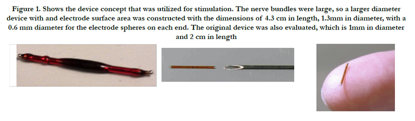
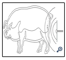
Our investigation explored the feasibility of powering wireless stimulators using microwave energy at 915 MHz, a frequency in the ISM band in the US [13]. The goal of our study was to demonstrate that electrical radiative coupling can be used effectively to provide analog power to wireless stimulators at tissue depths that are necessary for meaningful therapeutic neuromodulation applications in humans [14]. Small wireless bipolar stimulators, as shown in Figure 1, were implanted directly on to the sciatic nerve, allowing for a simple and immediate verification of device functionality through activation of downstream muscles. Additionally, the amount of current in tissue generated from the implant activation at various depths was measured to quantify the energy transfer between the transmitting antenna (Tx), external to the skin held in free space air or on the skin, and the receiving antenna (Rx) inside of the neural stimulator implant.
Experimental Methods
This section describes the experimental methods that were conducted. Implantation of the device on the sciatic nerve was performed on anesthetized pigs, ranging in weight from 95 kg to 120 kg. A wired electrode was used to determine the cathodic current required to reach motor threshold at each implant location.
The wireless stimulators were energized remotely after closure of the incision through overlying muscle and fat tissue excluding air. This substantial mass of conductive tissue provides an alternative (and relatively low-impedance) path for current to travel from the electrode and thus the total current required to reach threshold would be much higher than in the wired/open-air configuration [13].
Two wireless stimulators were built. The first device incorporated a2-cm dipole, where its length was approximately equal to the half-wavelength of a 915 MHz electromagnetic wave in muscle tissue. This was determined by the following: The wavelength λ is found from the relation:
Where c is the speed of light in the medium in m/s and f is the frequency in Hz. In free space, the wavelength is 32.8 cm at 915 MHz. In muscle tissue, the speed of light is roughly 1/8 that of free space and the wave length in muscle tissue is therefore correspondingly shorter, approximately 4.3 cm [14]. From antenna theory, an optimal dipole antenna is generally designed such that its total length is one half of the wavelength, which in this case would be 2.1 cm [15].
Accordingly, two implantable devices were investigated with 2 cm and 4 cm dipole antenna lengths. The stimulators used a very simple architecture comprised of placement of microelectronics for rectification connected to the center tap of an insulated dipole Rx antenna. This circuit is internal to the electrodes of the device. The ends of the antenna were exposed to tissue serve as stimulating electrodes, which were 0.6 mm diameter Pt-Ir hemispheres. These devices did not incorporate charge-balancing circuitry, but the Pt-Ir electrodes are believed to be largely capacitive in nature [16]. In design of the Tx antenna, coupling to the target tissue plays a primary role in the actual amount of power dissipation that occurs as the EM passes through the tissue. The optimal wavelength is determined by the relationship:
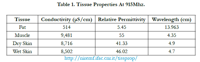
Where the variables are defined in (1), with the addition of the tissue conductivity, ε0, determined from previously reported values as summarized in Table 1 [17].

After determining the motor threshold for wired stimulation at each location, each wireless device was implanted serially in the exact site of the wired measurement. Wireless stimulators were implanted on the sciatic nerve with the cathode distal to the anode to remove the possibility of the anodic block affecting the propagation of the compound action potential (CAP).
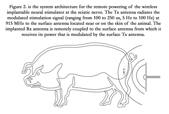
To provide remote power and programming to the implanted devices, the external Tx antenna was placed on the skin with an underlying layer of adipose tissue, as shown in Figure 2. The antenna was typically operated at a frequency of 915 MHz, wavelength 14 cm. During previous experiments, the Tx antenna length had been adjusted using trial and error by incrementally cutting down a longer dipole until the optimum response was achieved.
This “blind” optimization yielded an antenna length of 13.5 cm, which was kept for subsequent experiments involving the porcine model. A high-power microwave generator supplied the power to the Tx antenna. Precise determination of the relative power was not possible due to limitations of the instrument controls. In addition, reflected power from the Tx antenna (i.e. power sent backward into the transmitter) was measured, but not factored into the power emission levels, creating an artificially high amount of average power emission that is at least 50% greater than the actual power reaching the surface of the skin of the animal.
The microwave source was gated by a 9V pulse generator to 100 µs duration and repeated at intervals of 5Hz. When a microwave burst of sufficient amplitude is received by the wireless implant, the stimulator rectifies the 915 MHz signal, thus producing an axial current in the dipole Rx antenna. This current passes through the tissue via the electrodes at the ends of the dipole, creating a stimulus pulse that is sustained as long as the microwave power is supplied. In this feasibility study, 100µs pulse duration was used which is sufficiently long enough to excite motor axons. The goal of this approach was to keep the duty cycle sufficiently low (i.e. 100µs/5Hz) = 20µs/Hz.
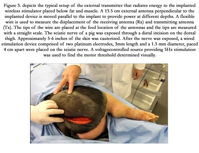
For a given position of the wireless stimulator on the sciatic nerve, the power of the external generator was swept until motor threshold was achieved, as shown in Figure 3. The power required to reach threshold was recorded as a function of the tissue thickness overlying the implant. The external Tx antenna was moved laterally farther away from the implant and a new threshold power was obtained at each location. On average, five depths were measured for a given implantation site. Four implantations were made on each leg. The axial current decreases as the depth to the implant increases in a non-linear fashion and then increases at a given point as the power to the external antenna is increased. Measurements made were:
- Sciatic stimulation versus probe measurement recorded with wired electrode
- Depth study with implant enclosed in tissue
- Depth with device coupled to tissue
- Depth study with coupled and isolated probe
Without an implant, the power of the transmitting antenna was swept to observe the reflection at different power levels. Measurements were taken and recorded at each location. It was observed that the reflection did not change when the device was placed and then removed from the tissue; indicating that the reflection was due to a mismatch between the impedance of the skin and the Tx antenna.
Results
Three animals were used for quantitative studies of the approximate transmitted power required for motor threshold versus the thickness of tissue overlying the implant. The following observations were made:
- The Tx antenna was shaped to match the body contour providing better power coupling.
- Different Tx antenna shapes provided different results. For instance, when a V shape was made with the different ends of the dipole, the antenna could be placed only inches from the skin and still energize the implanted stimulator.
- When only one side of the dipole was placed on the skin, activation of the stimulator was possible.
- The average amount of current required to achieve threshold activation for a wired stimulator was found to be 3.8 mA, with a range from 2 mA to 7 mA.
- Longer wireless devices had greater output, despite their being longer than a half-wavelength.
Discussion
Tissue depth measurements demonstrated that electromagnetic energy transmitted from a basic dipole antenna propagates through at least 12 cm of layered tissue. The tissue distribution consisted of layers of fat and skin, but primarily, muscle. Tank studies were run to confirm the results seen in the animal experiments. These tank studies permitted for a more controlled environment in which the impedance of the antennas could be match for a given tissue medium phantom.
The main sources of error in these animal studies are a result of reflection, which inaccurately skews the power needs, requiring a higher input level than if reflection were minimized with a properly shielded, directional antenna configuration (which was not used). In these tests, power was reflected from the antenna back to the transmitter, from the skin, from interfaces between layers of tissue, and from the Tx antenna it self.
Using a network analyzer, we demonstrated a -6dB reflection coefficient for the antenna on the skin. The reflection coefficient of the layers of tissue is dependent upon impedance changes due to the interface between tissue and the dielectric coefficient of the tissue layers themselves. The greatest reflection occurs at fat/muscle interface where the relative permittivity is 13 and 56 respectively for 915MHz. The Tx antenna input characteristics can be modified to match those of the internal circuitry to prevent reflection back into the transmitter, from the skin and implant, by matching the impedance in the transmitter output to the dipole. To minimize the reflection off the skin and improve the propagation through the skin, the antenna would need to include matching layers at the skin-antenna interface (in progress).
In addition to investigating the depths at which nerve activation could be achieved, current versus generated power was also quantified in this study. The efficiency of the antenna was determined by its geometry and radiation. In air, a half-wavelength is typically the desired length for obtaining the maximum radiated field perpendicular to the antenna. However, these parameters were not valid due to the near- field in a dispersive medium. In our case, we observed improved results with a full wavelength configuration.
The test setup can be analyzed when the directivity of the field and the three-dimensional nature of the radiation pattern are not taken into account. Depth measurement at this scale is assumed that the radiated energy flows as a ray from the feed location of the Tx antenna to the feed location of the implanted antenna. This assumption allows for a penetration depth of 12 cm when the antenna is moved along the skin. The contour of the animal is assumed have a negligible effect, and the antenna is assumed to point in the direction it is rotated. In this way, the horizontal distribution of the radiation pattern could be limited and hence, moving the antenna a certain distance away would move it outside of the radiation field. Because of the wide radiation pattern in the tissue, it is safe to assume that energizing a neural stimulator using the present system can be achieved at a maximum displacement of 12 cm.
Figure 5 shows the amount of average power necessary to achieve direct nerve activation at various depth levels. From 4 cm to approximately 8.5 cm, the average power required remained in the range of 200 to 300 mW. At depths greater than 8.5 cm, power levels steadily increased in a linear fashion to 800 mW at a depth of 12 cm.
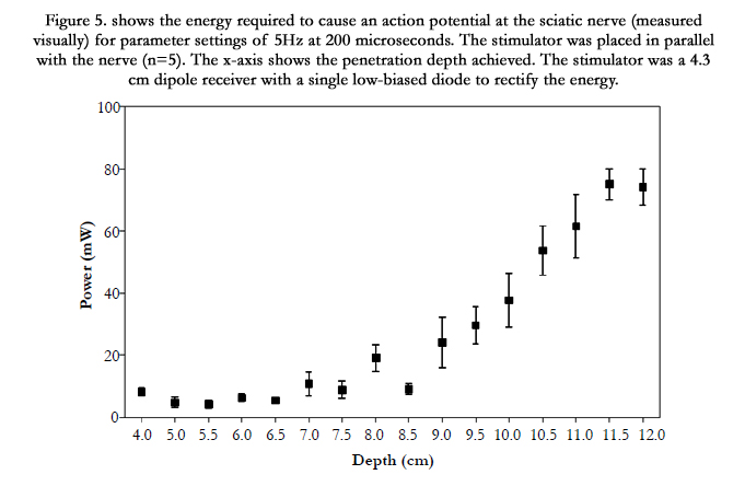
Figure 6 shows the average power necessary to achieve motor threshold. This power is significantly low because direct nerve stimulation does not require a large amount of current typically not greater than 1 mA. Therefore the average power at depths even up to 10 cm was less than 40 mW.
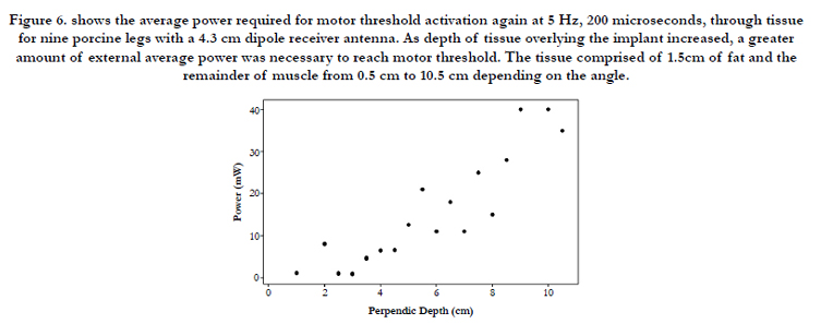
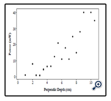
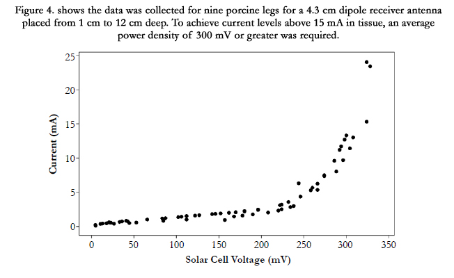
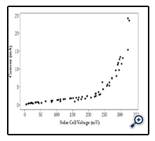
Figure 7 is perhaps the most important output measure, as this was a direct recording of the current generated at the electrode interface for various depth levels. An average maximum current of 10 mA was achievable at depths to 8 cm for an average power level of under 1 Watt.
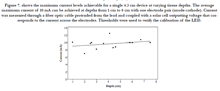
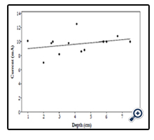
A linear regression between points for this data cannot be determined because of the non-linear interaction between the nearfield radiation pattern of the dipoles. Several factors can explain the differences in data across the samples, including the Tx antenna used, usually shaped by hand to fit over the body curvature. This results in different antenna impedances and radiation patterns for different data points in each animal sample.
The variance in data points from leg to leg might be explained by variable thicknesses of fat present on each leg. As the degree of curvature changed from animal to animal, so did the degree of distortion of the radiation pattern in the tissue. However, it was assumed that both the samples of each leg would have similar curves. In addition, because the motor threshold varies with time and with the location of the stimulator, there is an inherent variability present in the measurement system.
Conclusion
Dipole antennas operating at 915 MHz can energize wireless neural stimulators at a depth of up to 12 cm of soft tissue. The 4.3 cm implanted Rx antenna proved to be more efficient than a 2 cm antenna. This conclusion can be explained by the fact that the 4.3 cm length is closer to the estimated wavelength of the 915 MHz signal in tissue. From the animals used in this study, we profiled the tissue to consist of a mixed medium of muscle, fat, and skin. The thickness of the fat ranged from 1.5 cm to 2 cm. Reflection shows a 50% reflection of higher drives. Therefore, with a wellmatched external antenna, the device should be driven at half the power. Additionally, a patch antenna would be preferred, as it would guide energy in a single direction, cutting the power consumption in half once again, for 25% of the reported values here in to achieve the same results and current measurements.
References
- Poon, Ada, SO’Driscoll, THMeng (2009) A mm-Sized Implantable Power receiver with Adaptive Link Compensation. ISSCC Stanford University 294 – 295.
- Poon, Ada, SO’Driscoll, THMeng. (2010) “Optimal Frequency for Wireless Power Transmission Into Dispersive Tissue IEEE Trans Antennas Propag. 58(5): 1739 - 1750.
- Heetderks WJ. (1988) Microwave Powering of Millimeter- and sub millimeter- sized neural prosthetic implants. Nat. Inst. of Health, Bethesda, MD, USA.
- Cameron T, Liinamaa TL, Loeb GE, Richmond FJ (1998) “Long-Term Biocompatibility of a Miniature Stimulator Implanted in Feline Hind Limb Muscles.” IEEE Trans Biomed Eng, 45(8): 1024-1035.
- Chou, C. K., Bassen, H., Osepchuk, J., Balzano, Q., Petersen, R., Meltz, M., Cleveland, R., Lin, J. C., And Heynick, L. (1996) “Radio Frequency Electromagnetic Exposure: Tutorial Review On Experimental Dosimetry,” Bioelectromagnetics, 17(3): 195–206.
- Johnson, C. C., And Guy, A. W. (1972) “Nonionizing Electromagnetic Wave Effects In Biological Material And Systems.” Ieee Proceedings. 60(): 692–718.
- Stuchly M, Kraszewski A. (1985 ) Exposure of human models in the near field of and far field—A comparison. IEEE Transactions on Biomedical Engineering BME-32(8): 609 - 616.
- Kanda, M., and Driver, L. D. (1987) “An isotropic electric-field probe with tapered resistive dipoles for broad-band use, 100 kHz–18 GHz.” IEEE Transactions on Microwave Theory and Techniques, 35(2): 124–130.
- Masterson KD, Driver LD, Kanda M. (1989) Photonic probes for measurement of electromagnetic fields over broad bandwidths. IEEE National Symposium on Electromagnetic Compatibility Digest, Boulder, CO, USA.
- Naghski. DH, Boyd, JT, Jackson, HE, Sriram, S., and Kingsley, SA (1994) “An integrated photonic Mach-Zehnder interferometer with no electrodes for sensing electric fields.” J. Light Technol, 12(6): 1092–1098.
- Wyss, J. C., and Sheeran, S. T. (1985) “A practical optical modulator and link for antennas.” J. Lightwave Technol, 3(2): 316–321.
- Passour J, Hagmann M, Koves L, Jabari M, Hurt WD. (1995) Development of an RF current monitor to measure currents induced in the human body. US Air Force Occupational and Environmental Health Directorate, Brooks AFB, TX.
- Bassen, HI, Herchenroeder, P, Cheung, A, and Neuder SM (1977) “Evaluation of implantable electric field probes within finite simulated tissues.” Radio Science. 12(6(S)): 15–23.
- Stuchly, MA, Stuchly, SS, and Kraszewski, A (1984) “Implantable electric field probes, some performance characteristics,” IEEE Transactions on Biomedical Engineering. 31(7):526–531.
- Hagmann, M. J., and Babij, T. M. (1993) “Noninvasive measurement of current in the human body for electromagnetic dosimetry,” IEEE Trans. Biomed. Eng. 40(5): 418–423.
- Bickmore RW, Hansen RC. (1959 ) Antenna power densities in the Fresnel region. IRE Proceedings. 47: 2119–2120.
- Friis, HT (1946) “A Note on a Simple Transmission Formula,” Proc. IRE, 34( 5): 254 – 256.


