Point Absorber Wave Energy Converters in Regular and Irregular Waves with Time Domain Analysis
Fuat Kara*
School of Water, Energy and Environment, Cranfield University, UK.
*Corresponding Author
Fuat Kara,
School of Water,
Energy and Environment,
Cranfield University, UK.
E-mail: f.kara@cranfield.ac.uk
Received: November 28, 2016; Accepted: December 12, 2016; Published: December 15, 2016
Citation: Fuat Kara (2016) Point Absorber Wave Energy Converters in Regular and Irregular Waves with Time Domain Analysis. Int J Marine Sci Ocean Technol. 3(7), 74-85.
Copyright: Fuat Kara© 2016. This is an open-access article distributed under the terms of the Creative Commons Attribution License, which permits unrestricted use, distribution and reproduction in any medium, provided the original author and source are credited.
Abstract
A discrete control of latching is used to increase the bandwidth of the efficiency of the Wave Energy Converters (WEC) in regular and irregular seas. When latching control applied to WEC it increases the amplitude of the motion as well as absorbed power. It is assumed that the exciting force is known in the close future and that body is hold in position during the latching time. A heaving vertical-cylinder as a point-absorber WEC is used for the numerical prediction of the different parameters. The absorbed maximum power from the sea is achieved with a three-dimensional panel method using Neumann-Kelvin approximation in which the exact initial-boundary-value problem is linearized about a uniform flow, and recast as an integral equation using the transient free-surface Green function.The calculated response amplitude operator, absorbed power, relative capture width, and efficiency of vertical-cylinder compared with analytical results.
2.Introduction
3.Equation of Motion of Wave Energy Converters
4.Solution of Boundary Integral Equation
5.Latching Control of Offshore Wave Energy Converters
5.1. Numerical Results for Regular Waves
5.2. Numerical Results for Irregular Waves
6.Discussion and Conclusion
7.References
Keywords
Time Domain; Transient Free-Surface Green Function; Boundary Integral Equation; Absorbed Power; Relative Capture Width; Latching Control
Introduction
The issue of global warming has resulted in growing pressure to switch to renewable sources (e.g. solar, wind, wave, tidal, geothermal, ocean thermal etc.) to reduce carbon emissions. Of these, ocean wave power has received much attention in Europe and other part of the world. The global power potential represented by waves that hit all coasts worldwide is estimated to be in the order of 1 TeraWatt (TW) (Panicker [1]). If wave energy loss due to friction and wave breaking may be utilised, then the global wave power input is estimated to be one order of magnitude larger (≈10 TW), a quantity that is comparable with the world’s present power consumption. The idea of converting the energy of ocean waves into useful energy forms is not new. There are techniques that were first patented as early as 1799 (Girard [2]). The pioneer work for the wave energy utilisation was introduced by Masuda [3] in the late 1940s, Salter [4], Budal et al., [5], McCormick [6], Mei [7]. For an axisymmetrical WEC in regular waves, it is known that the maximum power that can be absorbed equals the incident wave power associated with a wave front of width one wave length divided by 2π. This result was first derived independently by Budal et al., [8], Evans [9] and Newman [10].
Power from ocean waves can be converted useful energy (e.g. electrical energy) by the use of Oscillating Water Columns (OWC) or Over Topping Devices (OTD) exploiting power of the sea water or oscillating devices (e.g. point absorber devices) in nearshore or offshore environment exploiting body motion of the devices which excited by the incident waves (Budal et al., [11]). OWC and OTD devices have large horizontal extension and large broad bandwidth whilst point absorber devices can take incident waves at any direction and have narrow bandwidth which allows the use of optimum control strategies (e.g. latching control) effectively. It is possible to convert wave energy to some other form; mechanical, hydraulic or pneumatic at very high efficiencies. The problem of converting this primary energy to a marketable product has presented the greatest challenge to various WEC inventors. The main reason for the very difficult engineering problems is the fact that waves transfer their energy in a slow irregular fashion whereas current technology, particularly for electrical generation, is more used to fast regular movements.
WEC without control traps energy only from the wave components whose frequency lays in the band of the natural frequencies of the system. Nevertheless, this system is potentially able to catch energy in the wave spectrum outside this band provided it can be dynamically controlled to adapt its bandwidth in real time. In this way, the power output from WEC can be increased by controlling the oscillation in order to approach an optimum interaction between WEC and incident wave. Optimum control methods can be classified for WEC as reactive (continuous) and latching (discrete) controls. Applying reactive control to WEC allows absorption of the maximum power (Salter et al., [12]). In reactive control, the applied force/moments are a continuous function of time, and generally include resistive and reactive components to approach resonance at wave frequencies lower than the natural frequency of WEC. In latching control (Budal et al., [11]) while the motion is locked, the wave exciting force continues to evolve. Latching control involves braking and releasing the oscillating body such that its velocity bears the desired phase relationship with the wave-applied exciting force.
The damping of WEC must be properly adjusted in order to obtain approximate optimum amplitude. This is accomplished by Power-Take-Off (PTO) system. PTO mechanism is idealized by damping coefficients, giving forces proportional to the velocity of WEC. In the context of mathematical modelling, since the objective with WEC is to induce a movement such that radiated waves cancel in amplitude and phase with the scattered component to a maximum extend, the accurate predictions of radiated and diffracted waves due to forced oscillation of WEC and exciting forces, respectively are crucially important. This ensures that as little energy as possible is in the resultant outgoing wave field and therefore the maximum energy is observed by WEC. The accurate and computationally efficient numerical model was developed by the author (Kara [13, 14]) for the prediction of the hydrodynamics and power characteristics of WEC in regular waves. In the present paper, latching control for vertical-cylinder as a wave energy converter will be used to maximize the absorbed energy from both regular and irregular ocean waves.
Equation of Motion of Wave Energy Converters
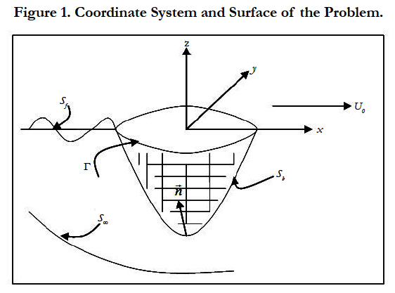
The right-handed coordinate system is used to define the fluid action. A Cartesian coordinate system x→ = (x, y, z) is fixed to the body. Positive x-direction is towards the bow, positive z-direction points upwards, and the z = 0 plane (or xy plane) is coincident with calm water. The body is translating through an incident wave field with velocity U0, while it undergoes oscillatory motion about its mean body surface position. The origin of the body-fixed coordinate system x→ = (x, y, z) is located at the centre of the xy plane. The solution domain consists of the fluid bounded by the free surface Sf (t), the body surface Sb (t), and the boundary surface at infinity S∞ as in shown in Figure 1.
Through Newton’s law, the dynamics of a floating body’s unsteady oscillations are governed by a balance between the inertia of the floating body and the external forces acting upon it. This balance is complicated by the existence of radiated waves; as a consequence both of the floating body’s own motions and its scattering of the incident waves. This means that waves generated by the floating bodies at any given time will persist indefinitely and the waves of all frequencies will be generated on the free surface. These generated waves, in principle, affect the fluid pressure field and hence the body force of the floating bodies at all subsequent times. This situation introduces memory effects and is described mathematically by a convolution integral. Having assumed that the system is linear, the equation of motion of any floating rigid body may be written in a form which is essentially proposed by Cummins [15].
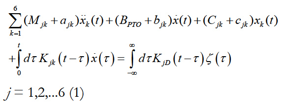
The displacement of the floating bodies from its mean position in each of its six rigid-body modes of motion is given xk in Eq.(1), and the overdots indicates differentiation with respect to time. The inertia matrix of the floating body is Mjk, damping due to PTO system is given as BPTO and linearized hydrostatic restoring force coefficients are given by Cjk. The radiation impulse response functions are composed of the hydrodynamic coefficients and the kernel of the convolution on the left-hand side of Eq.(1). A radiation impulse response function is the force on the body in the j-th direction due to an impulsive velocity in the k-th direction, with the coefficients ajk, bjk, cjk, accounting for the instantaneous forces proportional to the acceleration, velocity, and displacement, respectively, and the memory function Kjk(t) accounting for the free surface effects which persist after the motion occurs. For the radiation problem the term ‘memory function’ will be used to distinguish this portion of the impulse-response function from the instantaneous force components outside of the convolution on the left-hand side of Eq.(1). The term KjD(t) on the right hand side of Eq.(1) are the components of the exciting force and moment’s impulse response functions due to the incident wave elevation ζ0(t), defined at a prescribed reference point in the bodyfixed coordinate system. Here, the kernel KjD(t) is the diffraction impulse response function; the force on the body in the j-th direction due to a uni-directional impulsive wave elevation with a heading angle of β. Once the stiffness matrix, inertia matrix, and fluid forces e.g. radiation and diffraction forces are known, the equation of motion of floating body Eq.(1) may be solved using the fourth order Runge-Kutta method.
Solution of Boundary Integral Equation
The initial boundary value problem consisting of initial condition, free surface and body boundary condition may be represented as an integral equation using a transient free surface Green’s function (Wehausen and Laitone [16]). Applying Green’s theorem over the transient free surface Green function derives the integral equation. It is possible to show that transient free surface Green’s function satisfies the initial boundary value problem without a body (Finkelstein [17]). Integrating Green’s theorem in terms of time from -∞ to ∞ using the properties of transient free surface Green’s function and potential theory, the integral equation for the source strength on the body surface may be written as in Kara [18].
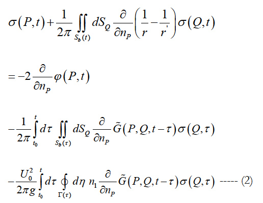
and potential on the body surface
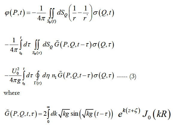
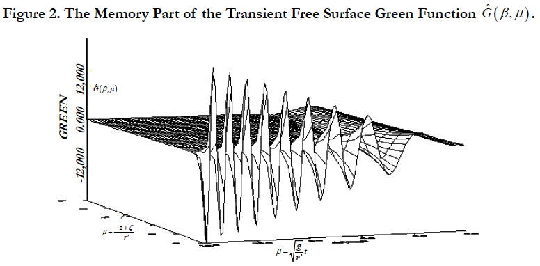
is the memory part of the transient free surface source potential, P(x(t), y(t), z(t)) the field point, Q(ξ (t),η (t),ζ (t)) the source point, r = √(x-ξ)2+(y-η)2+(z-ζ)2 the distance between field and source point and represent the Rankine part of the source potential, r' = √(x-ξ)2+(y-η)2+(z+ζ)2 the distance between field point and image point over free surface, J0 the Bessel function of zero order. The Green function G˜ (P,Q,t,τ ) represents the potential at the field point P(x, y, z) and time t due to an impulsive disturbance at source point Q(ξ, η,ζ) and time τ.
The integral equation for the source strength Eq.(2) is first solved, and then this source strength is used in the potential formulation Eq.(3) to find potential and velocities at any point in the fluid domain. The solution of the integral equation Eq. (2) is done using time marching scheme. The form of the equation is consistent for both the radiation and the diffraction potentials so that the same approach may be used for all potentials. Since the transient free surface Green function G˜ (P,Q,t,τ ) satisfies free surface boundary condition and condition at infinity automatically, in this case only the underwater surface of the body needs to be discretized using quadrilateral/triangular elements. The resultant boundary integral equation Eq. (2) is discretized using quadrilateral elements over which the value of the source strength is assumed to be constant and solved using the trapezoidal rule to integrate the memory or convolution part in time. This discretization reduces the continuous singularity distribution to a finite number of unknown source strengths. The integral equation Eq. (2) are satisfied at collocation points located at the null points of each panel. This gives a system of algebraic equations which are solved for the unknown source strengths. At each time step the new value of the source strength is determined on each quadrilateral panel.
The evaluation of the Rankine source type terms (e.g. 1/r, 1/r, ) in Eq. (2) is analytically integrated over quadrilateral panels using the method and formulas of Hess and Smith [19]. For small values of the integrals are done exactly. For intermediate values of r a multipole expansion is used. For large values of r a simple monopole expansion is used.
The surface and line integrals over each quadrilateral element involving the wave term of the transient free surface Green function G˜ (P,Q,t,τ ) are solved analytically (Liapis [20], King [21], Newman [22]) and then integrated numerically using a coordinate mapping onto a standard region and Gaussian quadrature. For surface elements the arbitrary quadrilateral element is first mapped into a unit square. A two-dimensional Gaussian quadrature formula of any desired order is then used to numerically evaluate the integral. The line integral is evaluated by subdividing Γ(t) into a series of straight line segments. The source strength σ(t) on a line segment is assumed equal to the source strength of the panel below it.
The evaluation of the memory part G˜ (P,Q,t,τ ) of the transient free surface Green function and its derivatives with an efficient and accurate method is one the most important elements in this problem. Depending on the values of P, Q, and t five different methods are used to evaluate G˜ (P,Q,t,τ ) ; power series expansion, an asymptotic expansion, a Filon integration quadrature, Bessell function, and asymptotic expansion of complex error function. Figure 2 shows the memory part G˜ (P,Q,t,τ ) of transient free surface Green function. The detail analysis of radiation and diffraction problem including Froude-Krylov force as well as numerical results that compared with analytical, experimental, and other published numerical results can be found in Kara [13, 14].
Latching Control of Offshore Wave Energy Converters
Latching control, which is a discrete real time control, will be used in the present paper. Rather than adapting WEC parameters to the excitation force in order to optimize the linear body response, the latching control adapts the body response to WEC and to the excitation in a nonlinear fashion. It is a kind of parametric resonance adaptation process as can be found in nonlinear oscillatory theory, this kind of behaviour can be predicted only using time domain simulations. Latching control can magnify the amplitude of the motion whatever the frequency of the excitation force, and can improve the efficiency of WEC in terms of absorbed energy for excitation frequencies. When latching control is applied, an additional force must be introduced in the dynamic of WEC to cancel the acceleration of the controlled motion in order to lock the system temporarily. The latching control of WEC consists of locking the oscillating body in position at the instant when velocity vanishes, and releasing it after a certain delay to be determined. This latching delay has to be applied in order to maximise the response amplitude of the body. The instant of latching is imposed by the dynamics of the body itself (i.e. vanishing velocity); thus the control variable is simply the duration of the latching phase, or equivalently the instant of release (Iversen [23], Greenhow et al., [24], Eidsmoen [25], Korde [26], Babarit et al., [27]). One of the advantages of latching control is that it is passive, which means that it does not need to deliver energy to WEC while it is engaged, since the forces do no work as long as the velocity vanishes.
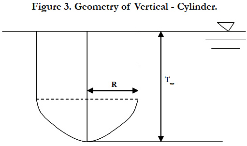
A vertical-cylinder with 8m radius R and 13m draft Tvc is used as an offshore floating wave energy converter in the following numerical results. The natural period Tn of the wave energy converter is 10s. Geometry of vertical-cylinder is given in Figure 3.
Budal & Falnes [11] point out that maximizing the extracted power requires that the wave force and the velocity of the wave energy converters be in phase. This condition is achieved when the velocity is vanishing. This implies that the wave energy converter is at its maximum displacement. The wave energy converter is hold until a prescribed time before the exciting force reaches its next extreme. This prescribed time is called the latching time which is a control variable. Our ITU-WAVE time domain program takes into account this latching strategy for a change in sign of the velocity which starts the latching.
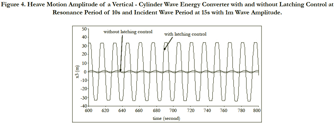
In Figure 4, the numerical simulation in the time domain of the body response with and without latching control is plotted. The huge magnification of the amplitude of the motion for the controlled system compared to the uncontrolled one is observed. The amplitude of the heave motion is increased more than by a factor of 20 in the case of latching control.
Figure 4. Heave Motion Amplitude of a Vertical - Cylinder Wave Energy Converter with and without Latching Control at
Resonance Period of 10s and Incident Wave Period at 15s with 1m Wave Amplitude.
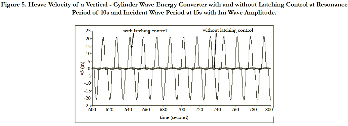
Figure 5 shows velocity of wave energy converter with 5s latching and without latching control. The device has 10s resonance frequency and incident wave period is 15s. One can observe a large amplification of the velocity of the device when latching control is applied as in motion amplitude of the heaving verticalcylinder in Figure 4.
Figure 5. Heave Velocity of a Vertical - Cylinder Wave Energy Converter with and without Latching Control at Resonance
Period of 10s and Incident Wave Period at 15s with 1m Wave Amplitude.
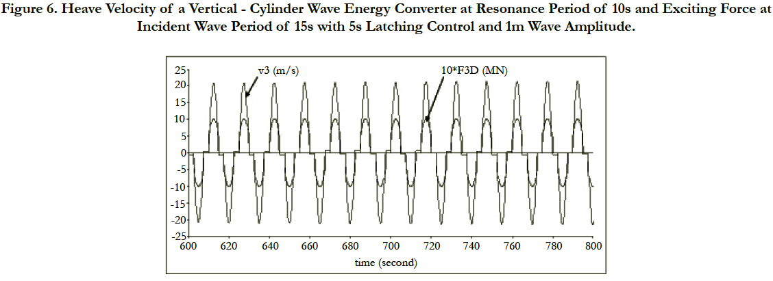
It is pointed out earlier that maximizing the extracted power requires that the wave force and the velocity of the wave energy converters be in phase when latching control is applied as shown in Figure 6. Latching duration can be observed from Figure 6.
Figure 6. Heave Velocity of a Vertical - Cylinder Wave Energy Converter at Resonance Period of 10s and Exciting Force at
Incident Wave Period of 15s with 5s Latching Control and 1m Wave Amplitude.
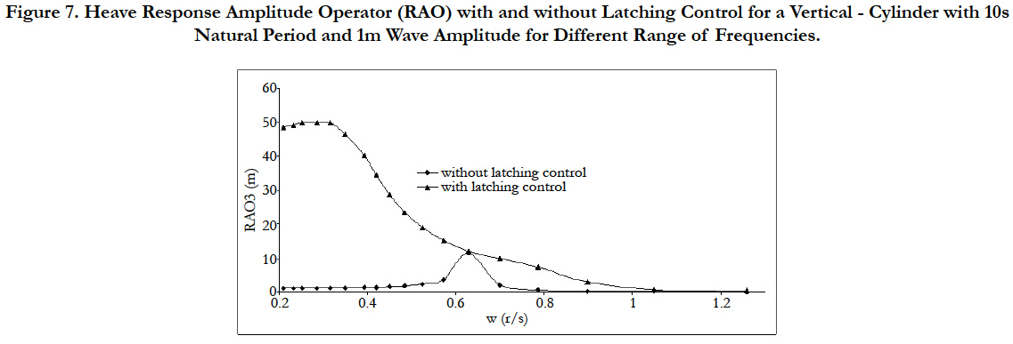
It is assumed that the excitation force is known in the future of the current computation time. The motion of a wave energy converter under latching control is a succession of the time of the rest and time of the transient. The control variable is the release (or unlatching) time or equivalently the latching duration. We pointed out earlier that the aim of the latching control is to maximize the amplitude of the oscillations of the device. This implicitly means that it will also maximize the absorbed power at the same time. Figure 7 shows an example of numerical simulation of the body motion in a different incident wave period with and without latching control. It can be seen that the amplifying effect of latching control is significant in Figure 7. It may be noticed from Figure 7 that the response amplitude can be as much as by a factor of 50 in the case of latching control in higher incident wave periods.
Figure 7. Heave Response Amplitude Operator (RAO) with and without Latching Control for a Vertical - Cylinder with 10s
Natural Period and 1m Wave Amplitude for Different Range of Frequencies.
A damping force
proportional to the velocity of the floating body is considered as the action of the external Power-Take-Off (PTO) mechanism. The instantaneous power converted by the wave energy converters is defined as:

where Pe is the power due to exciting force and Pr is the power due to radiation force.
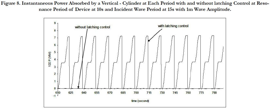
Figure 8 shows the instantaneous power absorbed for each incident wave period of 15s from ocean waves using a vertical-cylinder as a wave energy converter with and without latching control. In the case of latching control the absorbed instantaneous power is increased significantly. It may be noticed that the unlatching results are very small in terms of controlled latching results.
Figure 8. Instantaneous Power Absorbed by a Vertical - Cylinder at Each Period with and without latching Control at Resonance
Period of Device at 10s and Incident Wave Period at 15s with 1m Wave Amplitude.
The mean power P- extracted by the PTO over a time T range is given by:

The averaging time T must be much larger than the characteristics period of the wave, which is typically 5s to 15s. The maximum mean power that can be absorbed is equal to the linear damping proportional to velocity of the floating body. This is achieved when the velocity is in phase with the exciting force (Budal & Falnes [11]) as it is shown in Figure 6.
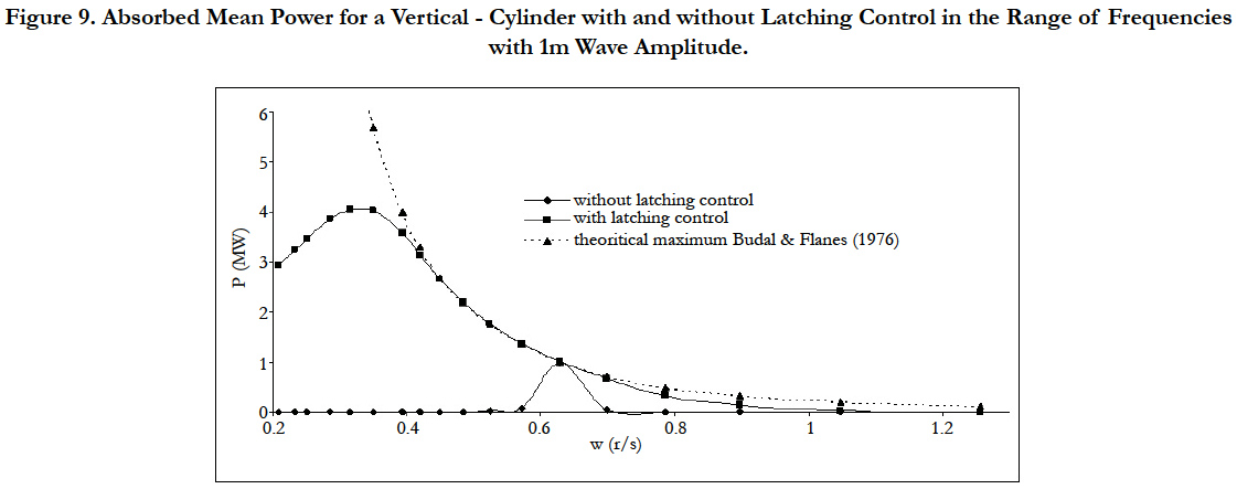
Figure 9 shows the absorbed mean power for the range of incident wave frequencies using a vertical-cylinder as a wave energy converter with and without latching control. In the case of latching control the absorbed mean power is again increased significantly. The theoretical maximum power absorption in regular seas is given by Budal and Falnes [11].
Figure 9. Absorbed Mean Power for a Vertical - Cylinder with and without Latching Control in the Range of Frequencies
with 1m Wave Amplitude.

where ζ0 being the incident wave amplitude and being incident wave frequency.
The capture width and maximum capture width lmax is defined as (Budal and Falnes [11]).

respectively where P-(t) is the mean power and given by Eq. (5), Pw = ρg2ζ2a/4ω is the wave power in the incident wave train per unit crest length, ζa being the incident wave amplitude. A good wave absorber is a body which has the ability when making waves, to concentrate the wave energy along a narrow sector rather than distribute the energy evenly over all angles. The maximum capture width equals to λ/(2π) for an axisymmetric system in symmetric mode of motion e.g. heave. This implies that the floating bodyabsorbs all the power in an incident wave equal to that passing a crest length of λ/(2π). Relative capture width is obtained by dividing capture width with width of the wave energy converters, lrcw = l/B.
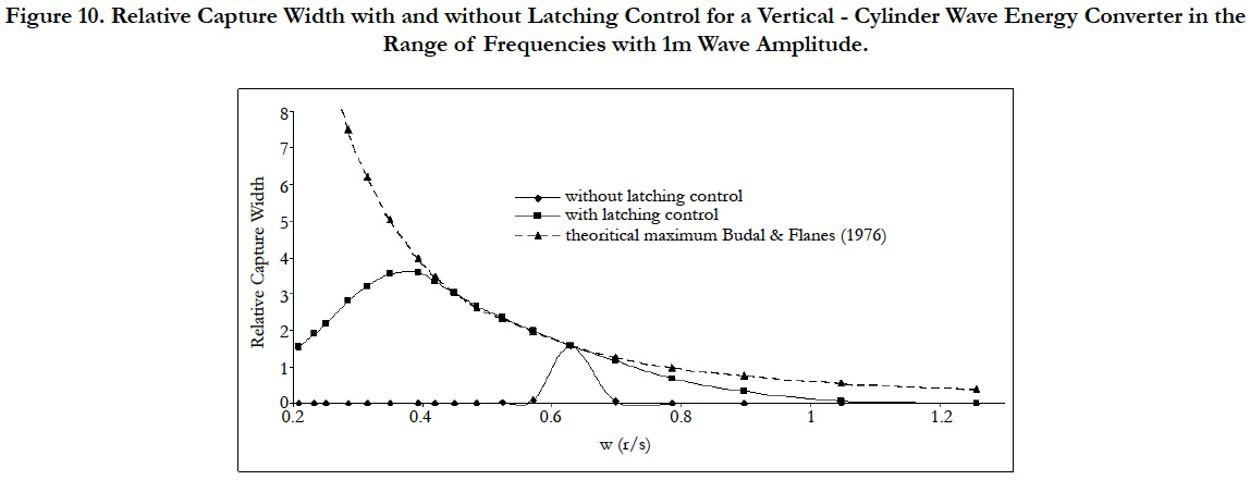
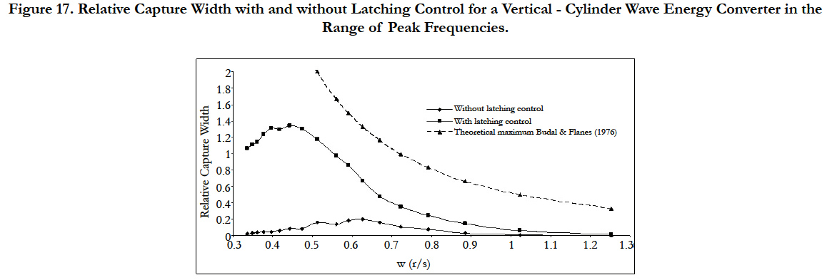
Figure 10 shows the relative capture width for with and without latching controlled system and the theoretical maximum in the context of linear theory are plotted. For such a single axisymmetric system in symmetric mode of motion e.g. heave, the maximum capture width as pointed out earlier equals to λ/(2π). It may be noticed that it means that for low frequency waves, the absorbed power can possibly be greater than the incident power in the width of the body, implying capture widths greater than 1 and this can be observed in Figure 10. It can be also observed that latching control allows an improvement of the relative capture width whatever the frequency of the incident waves are.
Figure 10. Relative Capture Width with and without Latching Control for a Vertical - Cylinder Wave Energy Converter in the
Range of Frequencies with 1m Wave Amplitude.
The efficiency η of wave energy converters is defined as η =l / lmax, which has a maximum of 1.0 for any wavelength.
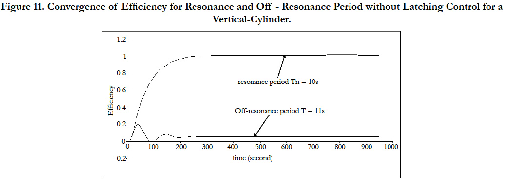
Figure 11 shows the efficiencies for vertical-cylinder in the case of in resonance and off-resonance periods. The efficiency converges to 1.0 (100% efficient) at resonance period Tn=10s whereas offresonance case T=11s shows a very low efficiency (5%).
Figure 11. Convergence of Efficiency for Resonance and Off - Resonance Period without Latching Control for a
Vertical-Cylinder.
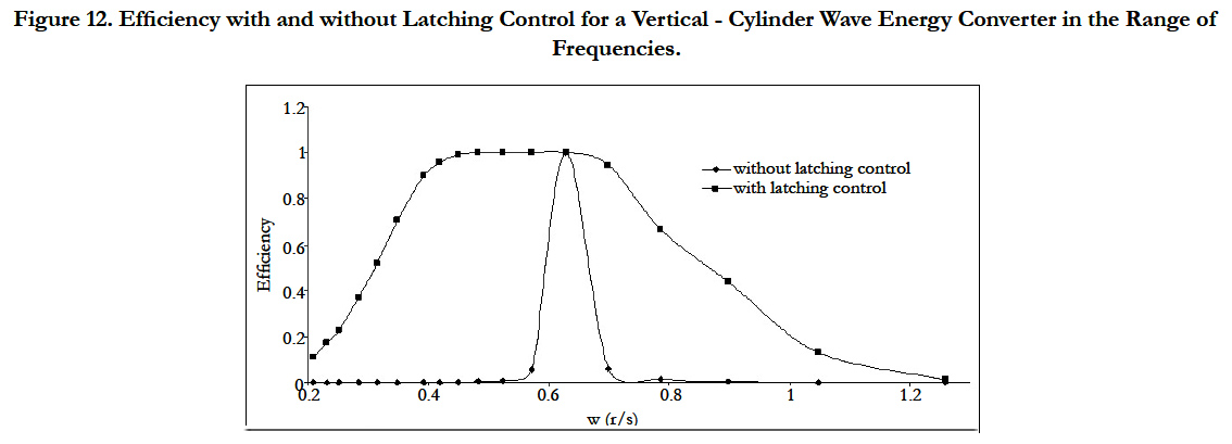
Figure 12 shows the efficiency plotted against the circular frequency for a vertical-cylinder which has 10s (0.628 rad/s) natural period. If the natural period of vertical-cylinder equals the period of incident waves in the case of without latching control, the device is perfectly tuned and we expect optimal efficiency. As the difference between natural period of device and incident wave period increases, the efficiency of the system decreases. As can be seen in Figure 12 latching control increases the bandwidth of the wave energy converter for all frequency ranges. If off-resonance period is 11s (0.571 rad/s), the efficiency is approximately 5% without latching control. However, if 1s latching is applied to vertical-cylinder wave energy converter, it is possible to achieve an efficiency of approximately 100%.
Figure 12. Efficiency with and without Latching Control for a Vertical - Cylinder Wave Energy Converter in the Range of
Frequencies.
The Pierson-Moskowitz spectral formulation (Pierson and Moskowitz [28]) developed from analysis of measured data obtained in the North Atlantic by wave recorders installed on weather ships will be used for irregular seas. Analysis for this spectrum was carried out only on selected wave records considered to have been acquired in fully developed sea. The Pierson-Moskowitz spectrum can be presented in terms of significant wave height Hs. That is,

The Pierson-Moskowitz spectral formulation depends on a single parameter, significant wave height, Hs. The relationship between significant wave height Hs and peak frequency ωp is given as ωp = 0.4 × √g / HS (Ochi [29]). The theoretical maximum power absorption in irregular seas is similar to the regular wave prediction and is given by Budal and Falnes [11]).

The benefit of the latching control depends on the spectral characteristics of the incident wave. A wave energy converter will work with wave environment in which peak period ωp is in the range of between 5s and 15s. The control variable that the body velocity vanishes remains invariant as in regular waves as well as the moment of unlatching in random sea environment.
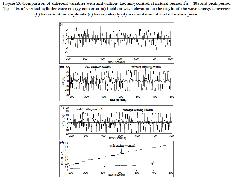
Figure 13 shows the incident wave height which is the input for the numerical calculation of the exciting forces of diffraction and Froude-Krylov forces, heave displacement and velocity of the wave energy converter which is the response of the floating structure in the case of with and without latching control, and accumulated instantaneous absorbed power from the ocean.
Figure 13. Comparison of different variables with and without latching control at natural period Tn = 10s and peak period
Tp = 10s of vertical-cylinder wave energy converter (a) incident wave elevation at the origin of the wave energy converter
(b) heave motion amplitude (c) heave velocity (d) accumulation of instantaneous power
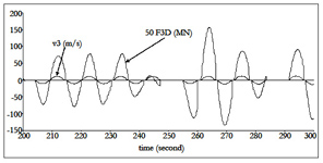
Figure 14 shows the velocity and exciting force in phase in irregular wave case. The same strategy as in regular sea is used e.g. vanishing velocity that starts latching duration.
Figure 14. The Velocity and Exciting Force of Heaving Vertical - Cylinder at Natural Period Tn = 10s and Peak Period
Tp = 10s.
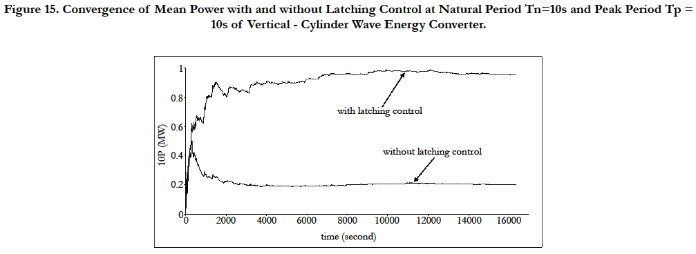
Figure 15 shows the convergence of the mean power. Prediction of the mean power for regular and irregular seas is done differently. In the case of regular seas, mean power is calculated for each incident period (Figure 8), while the accumulation of the instantaneous power is used for the irregular seas. It may be noticed in Figure 15 convergence of mean power requires more time in the case of irregular seas.
/
Figure 15. Convergence of Mean Power with and without Latching Control at Natural Period Tn=10s and Peak Period Tp =
10s of Vertical - Cylinder Wave Energy Converter.
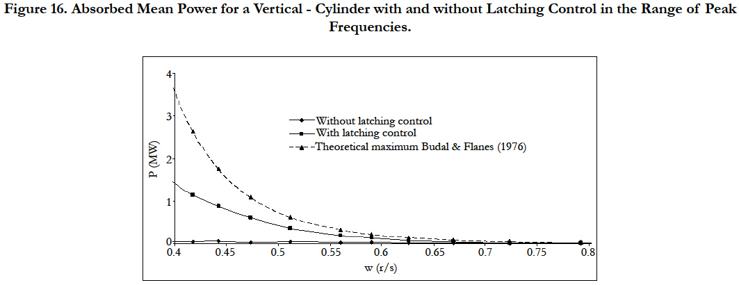
Figure 16 shows the absorbed mean power for the range of peak frequencies using a vertical-cylinder as a wave energy converter with and without latching control. In the case of latching control the absorbed mean power is again increased significantly.
Figure 16. Absorbed Mean Power for a Vertical - Cylinder with and without Latching Control in the Range of Peak
Frequencies.
Results are plotted in terms of relative capture width in Figure 17 as a function of the peak frequencies. For each result the relative capture width of the same device without latching control is represented for the purpose of comparisons. As it is compared to the regular seas, the relative capture width is reduced almost 37% and occurs in higher peak frequencies.
Figure 17. Relative Capture Width with and without Latching Control for a Vertical - Cylinder Wave Energy Converter in the
Range of Peak Frequencies.
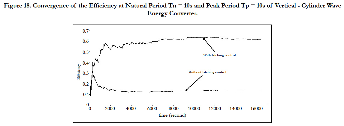
Figure 18 shows convergence of the efficiency of wave energy converters in time at around peak frequency of 10s with and without latching control. As compared to regular seas, the convergence of efficiency needs more time. One of the reasons for this is that the accumulation of instantaneous power is used for the irregular seas rather than calculation of instantaneous power for each period.
Figure 18. Convergence of the Efficiency at Natural Period Tn = 10s and Peak Period Tp = 10s of Vertical - Cylinder Wave
Energy Converter.
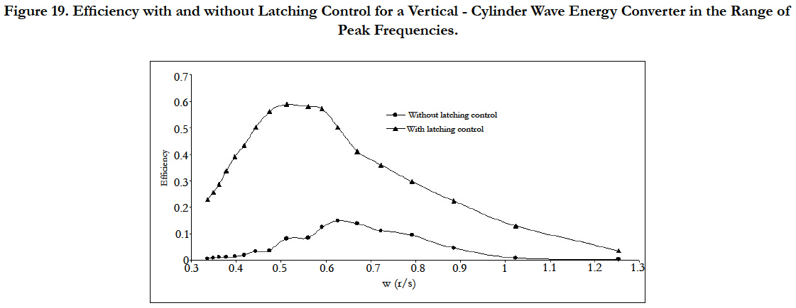
Figure 19 shows the efficiency of vertical-cylinder with and without latching control. The general trend shows that latching control improves considerably the efficiency of the wave energy converters especially as the peak frequency of the wave environment increases. The maximum efficiency in irregular seas is around 60% as it is compared to 100% in regular seas.
Figure 19. Efficiency with and without Latching Control for a Vertical - Cylinder Wave Energy Converter in the Range of
Peak Frequencies.
Discussion and Conclusion
A latching control with a transient hydrodynamic code for wave energy converters are used for the prediction of maximum power absorption from ocean waves for a point absorber heaving vertical-cylinder. Results have been presented to demonstrate the convergence of the method for power prediction of the floating wave energy converter and the calculation are shown to be in satisfactory agreement with analytical results. Results show that the efficiency of wave energy converters is considerably improved by the latching control which enlarges the bandwidth of WEC especially in the low frequencies, if the exciting force is predicted in the close future of the unlatching time.
Three topics for the future are given as follows; firstly, the efficient inviscid flow calculation techniques, such as Boundary Integral Equation (BIE) methods (Kara et al., [30-32], kara [33-35]) are well developed and routinely used in the design and analysis of marine hydrodynamics problems. Not only do BIE methods reduce the size of the numerical problem, but they eliminate, such issues as, 3D gridding of flow field and far field boundary conditions when the freesurface wave Green function methods are used e.g. transient wave Green function (Kara [33-35]) which is used in the present paper. While these methods robust and can provide reasonable answers quickly, they are incapable of predicting viscous effects. Damping arising from viscous effects, which reduce the efficiency of WEC, needs to be included and uses of Computational Fluid Dynamics (CFD) models (e.g. Direct Numerical Simulation (DNS), Large Eddy Simulation (LES)) will lead to a better solution. With these models, it is possible to give a realistic resolution of the flow field around WEC, hence opens the opportunity to have a more correct forcing including pressure and viscous on WEC. Although the numerical solutions of the CFD models have become more practical in recent years, it still requires considerable computational effort and is still not generally available for routine applications today. The viscous flows can be computed more efficiently using Viscous-Inviscid Interaction methods.
Secondly, a variational formulation called optimal command, which is an optimization problem; approach in time domain based on Pontryagin’s maximum principle (Hoskin et al., [36], Korde [26]) can be used in order to maximize the Hamiltonian at each time step for the optimum control of the WEC. Practically, it is computed by an iterative process. The latching control, which is an absolute bang-bang strategy meaning that optimal command has to be equal to its extremal values (0 or 1) in order to maximise Hamiltonian, has to be formulated by a weaker model to implement this theory with a good numerical efficiency. When absolute latching control is applied, a force is applied on the body that instantaneously cancels the acceleration of the motion in order to lock the system temporarily. In the weak modelling, this force is replaced by a very large (but not infinite) damping force. Thus, latching control is modelled by adding a large control force in the equation of motion. The main advantage of optimal command is that it can straightforwardly deal with random waves as well as regular waves and can be used with any kind of WEC. In addition, optimal command method can be used to assess the benefit that latching control can bring to the efficiency of WEC. A major interest of this method is that it can deal with WEC with more than one degree of freedom provided the equations of motion are written under a state form in regular and irregular waves in order to apply optimal control theory. In the time domain, non-linear components of forces (like hydraulic Power-Take-Off) can be introduced straightforwardly.
Finally, the optimisation problem of maximising the absorbed wave power is more complicate for a system of several modes of oscillation than for systems with a single degree of freedom as it was the case in the present paper. Multi-degree of freedom power exchange systems is more difficult to asses since power may also be exchanged from one degree of freedom to another.
/
Latching control can be used to improve the power absorption in random waves for multi-degree of freedom of WEC. Latching control results in two main effects: it enlarges the bandwidth of WEC especially in the low frequencies as it is shown in the present paper and it improves the absorption for the frequencies between the natural frequencies of WEC. Time domain strategies of motion control of WEC are in general applied only to single degree of freedom WEC. The reason to apply these strategies only to single degree of freedom WEC is that it is more difficult to find an efficient time domain strategy to compute latching control in a random sea for a multi degree of freedom WEC. The optimal command method, which can be used with any kind of WEC, is therefore a very useful tool to compute optimally controlled time domain series which then can be used in order to develop strategies which need less prediction of the future of excitation force.
References
- Panicker NN (1976) Power resource potential of ocean surface waves. Proceedings of the wave and salinity gradient workshop, UAS. J1-J48.
- Girard (1799) French Patent (translated by AE Hidden). Queens University, Belfast, UK.
- Masuda Y (1986) An experience of wave power generator through tests and improvements. Hydrodynamics of ocean wave energy utilization. 445-452.
- Salter SH (1974) Wave power. Nature. 249: 720-724.
- Budal K, Falnes J (1974) Proposals for conversion of the energy in ocean waves. Internal Report, Norwegian University of Science and Technology, Norway.
- McCormick M (1974) Analysis of a wave-energy conversion buoy. J Hyd. 8(3):77- 82.
- Mei CC (1976) Power extraction from water waves. J Ship Res. 20(2): 63-66.
- Budal K, Falnes J (1975) A resonant wave point absorber of ocean waves. Nature. 256: 478-479.
- Evans D (1976) A theory for wave-power absorption by oscillating bodies. J Fluid Mech. 77(1): 1-25.
- Newman JN (1976) The interaction of stationary vessels with regular waves. Proceedings of the Eleventh Symposium on Naval Hydrodynamics. 491- 501.
- Budal K, Falnes J (1976) Optimum operation of wave power converter. Internal Report, Norwegian University of Science and Technology, Norway.
- Salter SH, Jeffery DC, Taylor JRM (1976) The architecture of nodding duck wave power generators. Naval Architect. 21-24.
- Kara F (2010) Time Domain Prediction of Power Absorption from Ocean Waves with Latching Control. Renew Energy. 35(2): 423-434.
- Kara F (2016) Time Domain Prediction of Power Absorption from Ocean Waves with Wave Energy Converters Arrays. Renew Energy. 92: 30-46.
- Cummins WE (1962) The Impulse Response Function and Ship Motions. Shiffstechnik. 9: 101-109.
- Wehausen JV, Laitone EV (1960) Surface Waves. Handbuch der Physik. 9: 446-778.
- Finkelstein AB (1957) The Initial Value Problem for Transient Water Waves. Comm Pure Appl Math. 10(4): 511-522.
- Kara F (2000) Time Domain Hydrodynamics and Hydroelastic Analysis of Floating Bodies with Forward Speed. Ph.D. Thesis, University of Strathclyde.
- Hess JL, Smith AMO (1964) Calculation of Non-Lifting Potential Flow About Arbitrary Three-Dimensional Bodies. J Ship Res. 8: 22-44.
- Liapis S (1985) Time Domain Analysis of Ship Motions. Report No.302. The Department of Naval Architecture and Marine Engineering, The University of Michigan, Ann Arbor, Michigan.
- King B (1987) Time Domain Analysis of Wave Exciting Forces on Ships and Bodies. Report No.306. The Department of Naval Architecture and Marine Engineering, The University of Michigan, Ann Arbor, Michigan.
- Newman JN (1990) The Approximation of Free Surface Green Functions. Proceedings of the Fritz Ursell Retirement Meeting, Manchester, England , 107-135.
- Iversen LC (1982) Numerical method for computing the power absorbed by a phase-controlled point absorber. Appl Ocean Res. 4(3): 173-180.
- Greenhow M, White SP (1997) Optimal heave motion of some axisymmetric wave energy devices in sinusoidal waves. Appl Ocean Res. 19(3):141-159.
- Eidsmoen H (1998) Tight-moored amplitude limited heaving buoy wave energy converter with phase control. Appl Ocean Res. 20: 157-161.
- Korde UA (2002) Latching control of deep water wave energy device using an active reference. Ocean Eng. 29 (11): 1343-1355.
- cBabarit A, Duclos G, Clement AH (2004) Comparision of latching control strategies for a heaving wave energy device in random sea. Appl Ocean Res. 26: 227-238.
- Pierson WJ, Moskowitz LA (1964) A proposed spectral form for fully developed wind seas based on the similarity theory of A. A. Kitaigorodskii. J Geophysical Res. 69(24): 5181–5190.
- Ochi MK (1998) Ocean Waves: A Stochastic Approach. Cambridge Ocean Technology Series.
- Kara F, Vassalos D (2003) Time Domain Prediction of Steady and Unsteady Marine Hydrodynamic Problem. Int Shipbuild Progr. 50(4): 317-332.
- KaraF, Vassalos D (2005) Time Domain Computation of Wave-making Resistance of Ships. J Ship Res. 49(2): 144-158.
- Kara F, Vassalos D (2007) Hydroelastic Analysis of Cantilever Plate in Time Domain. Ocean Eng. 34(1): 122-132.
- Kara F (2011) Time Domain Prediction of Added Resistance of Ships. J Ship Res. 55(3): 163-184.
- Kara F (2015) Time Domain Prediction of Hydroelasticity of Floating Bodies. Appl Ocean Res. 51: 1-13.
- Kara F (2016) Time Domain Prediction of Seakeeping Behaviour of Catamarans. Int Shipbuild Progr. 62(3-4): 161-187.
- Hoskin RE, Nichols NK (1986) Optimal strategies for phase control of wave energy devices. Utilization of ocean waves: Wave to energy conversion. 184- 189.

