Comparative Study of Berthing Mechanism and Optimum Fender System for RCC Pile Supported Wharf as Per Indian Standard IS4651 Part-3:1974 and British Standard BS6349 Part-4:1994
Shah D1*, Patel M2
1 Sr. Assistant Professor, Faculty of Technology, CEPT University, Ahmedabad, Gujarat, India.
2 Director, Global Marine Consultants, Ahmedabad, Gujarat, India.
*Corresponding Author
Dhara Shah,
Sr. Assistant Professor, Faculty of Technology,
CEPT University, Ahmedabad – 380015, Gujarat, India.
Tel: +919727792830
E-mail: dharashah@cept.ac.in
Received: August 06, 2016; Accepted: September 07, 2016; Published: October 06, 2016
Citation: Shah D, Patel M (2016) Comparative Study of Berthing Mechanism and Optimum Fender System for RCC Pile Supported Wharf as Per Indian Standard IS4651 Part-3:1974 and British Standard BS6349 Part-4:1994. Int J Marine Sci Ocean Technol. 3(6), 55-73.
Copyright: Shah D© 2016. This is an open-access article distributed under the terms of the Creative Commons Attribution License, which permits unrestricted use, distribution and reproduction in any medium, provided the original author and source are credited.
Abstract
Berthing force is a critical dynamic lateral force in design of berthing structures, having equal relevance when compared to seismic forces. Besides, the construction costs of berthing structures are very high which can be optimized by selecting proper fender system. In the present study, berthing mechanism of bulk carriers having size from 5000 DWT to 250000 DWT is compared as per Indian Standard (IS) and British Standard (BS) so as to design an optimum fender system for a pile supported wharf. It is observed that British standard gives more precise values for berthing velocities for different vessel sizes and metocean conditions. Moreover, Indian Standard provides constant value of berthing velocity for vessel sizes more than 250000 DWT, which is not the case with British Standard. Comparative charts are prepared to understand the disparity in energy absorption capacity of different fender system for different vessel sizes and metocean conditions along with its consequences on the wharf. Study concludes with the preparation of suitability matrix, serving as a ready reckoner for selection of fender system for different size of vessels and metocean conditions.
2.Introduction
3.Vessel Characteristics and Different Fender Systems
4.Berthing Energy Calculation
4.1.Berthing Energy as per Indian Standard
4.2.Berthing Energy as per British Standard
5.Problem formulation
6.Design Berthing Force on Bulk Carriers
7.Post Analysis Result
8.Results and Discussions
9.Conclusions
10.References
Keywords
Bulk Carriers; Berthing Energy; Fender Systems; Berthing Velocity; Pile Supported Wharf; Dead Weight Tonnage.
Introduction
Maritime transport is one of the most important logistical systems, supporting universal movement of passengers and cargos cost effectively, thereby acting as a backbone for economic growth of country. The most common type of merchant ships used for freight transport are bulk carriers, container vessels, oil tankers, gas carriers, RORO ships, general cargo carriers, military ships and coastal trading vessels. Looking to the diversity of merchant ships visiting a particular port in view of their size, dead weight tonnage and type of cargo they carry, an adequate berthing facility is must to minimize the large impact spectrum of these vessels in terms of lateral force. India currently has 13 major and 187 minor ports. Nearly 95% of foreign trade by volume and 70% by value takes place through ports [3]. Newer ports are flourishing at a rapid pace in terms of cargo movement and hence a suitable understanding of berthing aids is essential for safe and economical berthing facilities.
Berthing force is one of the major forces accounted for the design of port structures. Various literature and design standards reveal that it might be a prevailing force in combination with other forces compared to seismic force. Berthing a vessel demands its kinetic energy to be absorbed/dissipated to avoid structural or vessel damage, which is done through buffers mounted on berthing structures, known as fenders. Fender systems work on the principle of high energy absorption and low reaction force. This reaction force is the design berthing force for the wharf and is a function of the size and type of fender units selected [13]. The reaction force can be obtained from energy-deflectionreaction diagrams of the fender system, provided by the fender manufacturer as shown in Figure 1 [14]. Higher the energy absorption of the fender system, lower is the lateral force on berthing structure. Selection of a wrong fender system does impact the life, safety and efficiency of the berthing structure. Hence it becomes vital to select an optimum fender system, designed and manufactured as per the functional and operational requirements of the specific port and terminal in order to optimize significant investment made, reduce interruption and maintenance needs as well as maximizing fender’s desired service life. Selecting an appropriate fender system does have a major impact on the overall project cost. This study will provide clear understanding about the consequences of berthing reaction of various fender systems in a prevailing berthing condition on pile supported wharf.
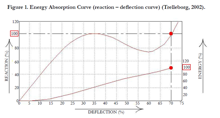
Figure 1. Energy Absorption Curve (reaction – deflection curve) (Trelleborg, 2002).
Vessel Characteristics and Different Fender
Systems
Appropriate vessel information is must to estimate the berthing energy of a vessel. Critical inputs pertaining to vessel in order to calculate berthing energy are vessel size, shape and mass. In the present study, berthing mechanism of bulk carriers with sizes from 5000 DWT to 250000 DWT has been considered. The statistical information for the vessels considered is given in Table 1 below. DWT is the dead weight tonnage i.e. the weight in tons of cargo, stores, fuel, passengers and crew carried by the vessel when loaded to her maximum summer load line. Displacement tonnage-DT is the actual weight of the vessel or the weight of T water she displaces when afloat and may be either ‘loaded’ or ‘light’. Displacement, loaded is the weight, in long tons, of the ship and its contents when fully loaded with cargo, to the Plimsoll mark or load line. Displacement, light, is the weight, in long tons, of the ship without cargo, fuel and stores.
Cell fender system, cone fender system, arch fender system, pneumatic fender system, parallel motion fender system, unit element fender system and V-type fender system are included in the present study, referring Trelleborg catalogue, approved by PIANC guideline for fender design 2002.
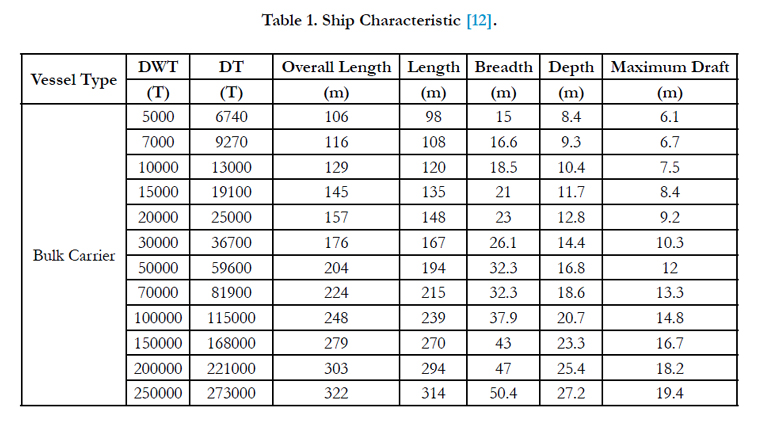

Table 1. Ship Characteristic [12].
Berthing Energy Calculation
According to Indian standard IS4651 part-3 [11], the design berthing energy is given as:
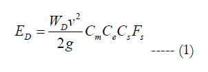
where,
WD = Displacement tonnage (DT) of the vessel in tonne
v = Approach velocity of the vessel in m/s, normal to berth
g = Acceleration due to gravity in m/s²
Cm = Mass coefficient
Ce = Eccentricity coefficient
Cs = Softness coefficient: 0.95 for soft fenders and 0.9 for hard fenders
Fs = Factor of safety = 1.4
Indian standard has specified five metocean berthing conditionsas shown in Table 2.
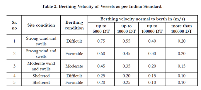
Table 2. Berthing Velocity of Vessels as per Indian Standard.
As per Indian standard, Cm depends on the size as well as displacement tonnage of the vessel and is calculated as:
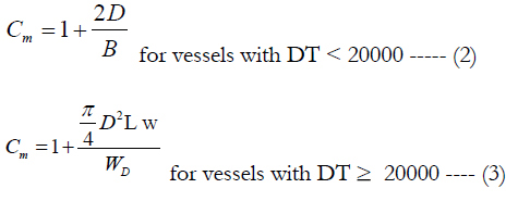
where,
D = Fully loaded draught of the vessel in m
B = Beam of the vessel in m
L = Length of the vessel in m
w = unit weight of water = 1.03 tonne/m³ for sea
WD = Displacement tonnage of the vessel in tonne
The eccentricity coefficient - Ce is calculated as:
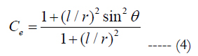
where,
l = Distance from the center of gravity of the vessel to the point of contact projected along the water line of the berth in m as shown in Figure 2.
r = Radius of gyration of rotational radius on the plane of the vessel from its center of gravity in m.
θ = Approach angle of the vessel
Indian standard provides eccentricity coefficient values for different l/r ratio as shown in Table 3.
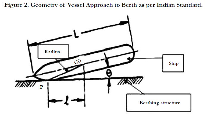
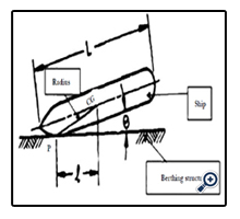
Figure 2. Geometry of Vessel Approach to Berth as per Indian Standard.
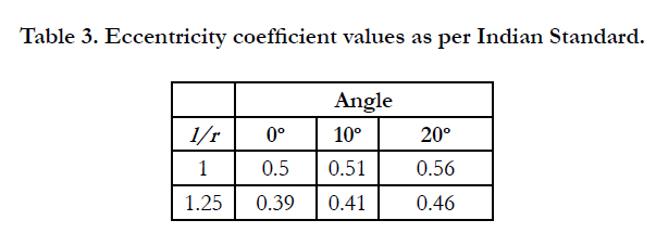
Table 3. Eccentricity coefficient values as per Indian Standard.
According to British Standard BS6349 part-4 [1], the design berthing energy is given as:
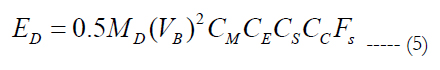
where,
MD = Displacement tonnage (DT) of the vessel in tonne
VB = Approach velocity of the vessel in m/s, normal to berth
CM = Hydrodynamic mass coefficient
CE = Eccentricity coefficient
CS = Softness coefficient: between 0.9 and 1.0
CC = Berth configuration coefficient
Fs = Factor of safety = 2.0
British standard has specified five berthing velocities as per the navigation conditions and size of the vessel as shown in Figure 3. The navigation conditions are:
a). Good berthing, sheltered
b). Difficult berthing, sheltered
c). Easy berthing exposed
d). Good berthing, exposed
e). Navigation conditions difficult, exposed
British standard has specified berthing velocity of vessel with respect to site conditions in graphical form. Each curve represents different navigation condition. Hence interpolated values can be obtained for intermediate size of vessels having different navigation conditions. British standard gives precise values of berthing velocity as compared to Indian standard.
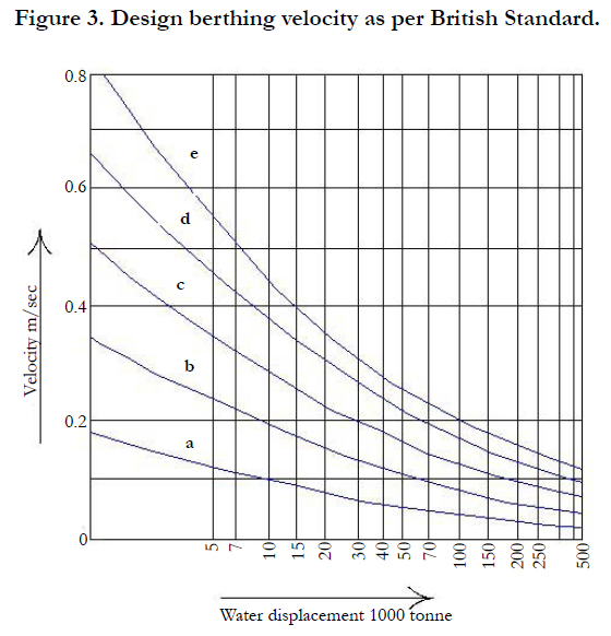
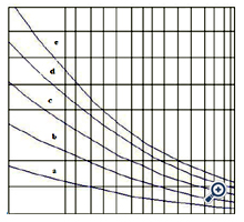
Figure 3. Design berthing velocity as per British Standard.
As per British standard, CM for any size of vessel is calculated as:
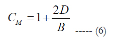
where,
D = Fully loaded draught of the vessel in m
B = Beam of the vessel in m
CM value generally ranges from 1.3 to 1.8 as per the above formula.
As per British standard, the eccentricity coefficient - CE, is calculated as:
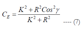
where, K= Radius of gyration of the vessel and is calculated as:
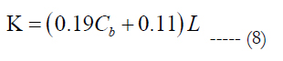
where,
L = Length of the hull between perpendiculars
Cb = Block coefficient, a function of hull shape and is given as:
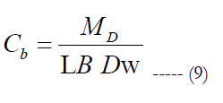
where,
MD = Displacement tonnage (DT) of the vessel in tonne
L = Length of the hull between perpendiculars
B = Beam of the vessel in m
D = Fully loaded draught of the vessel in m
w= unit weight of water = 1.03 tonne/m³ for sea
D = Distance of point of contact of vessel from the center of
mass in m
γ = Angle between the line joining point of contact to the center of mass and the velocity vector as shown in Figure 4.
British standard lists typical ranges of value for the block coefficient for various vessel types as shown in Table 4.
As per British standard, for open piled jetty structure, CC is taken as 1.0 whereas for a solid quay wall, CC is taken in between 0.8 and 1.0.
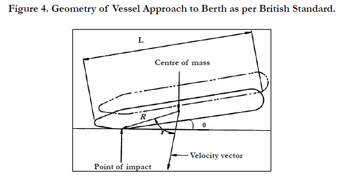
Figure 4. Geometry of Vessel Approach to Berth as per British Standard.
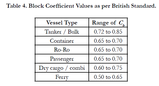
Table 4. Block Coefficient Values as per British Standard.
Problem formulation
A typical pile supported wharf module 25m wide and 45.805m long, housing bulk carriers is selected for the present study.The site is assumed to be in seismic zone V with Maximum Considered Earthquake (MCE) as 0.36g and Design Base Earthquake (DBE) as 0.18g as per IS1893 part-1 [7]. The wharf is constructed with precast/in-situ RC beamswith 0.5m thick deck supported on 40 bored cast in-situ piles having 1m diameter. Pile spacing is 6 m in longitudinal and transverse direction. Size of main beam is 0.5m x 1.5m whereas the size of pile muff is 1.5m x 1.5m respectively. The size of fender block is 1.5m x 1.5m x 8.24m. 75mm thick wearing coat is assumed on the deck. Design current velocity of 1.0m/s in the critical direction is considered.Marine growth of 50mm on piles is taken into account. Maximum and minimum recorded tidal levels are + 5.0 m and 0.0m at the proposed site, per Indian Naval Chart (Admiralty). Tidal levels are incorporated in the numerical model while applying wave force, berthing force, current force and hydrodynamic force on the wharf, at high tide level and low tide level. Other primary forces taken into consideration are Dead load and Live load [11]. Current force is calculated as per IRC6 [4]. Wave force on wharf is calculated using shore protection manual [2]. Hydrodynamic force is calculated as per IS1893 [6]. Berthing force is calculated as per IS4651 part-3 [11] with reference to PIANC guidelines and Trelleborg catalogue for fender systems. The wharf is designed and detailed for the load combinations using above forces, as per IS4651 part-4 [10]. Type of soil assumed is medium. M40 grade of concrete mix, having characteristic compressive strength fck as 40 MPa of 150 mm cube at 28 days [9] and Fe500 steel reinforcement having minimum yield stress fy as 500 MPa [5] is used. The wharf profile and layout is shown in Figure 5 and Figure 6. 3D models of wharf are prepared in STAAD software. Beams and piles are modeled using frame element. Pile fixity depth approach has been considered to define support as per IS2911 [8].
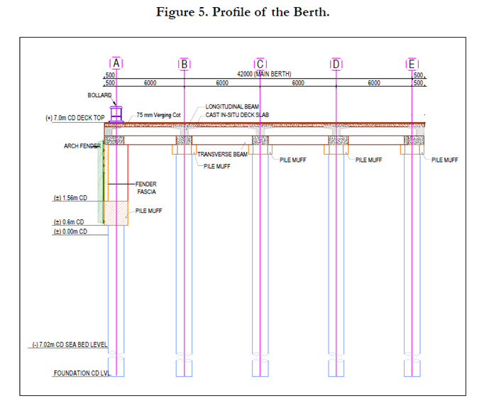
Figure 5. Profile of the Berth.
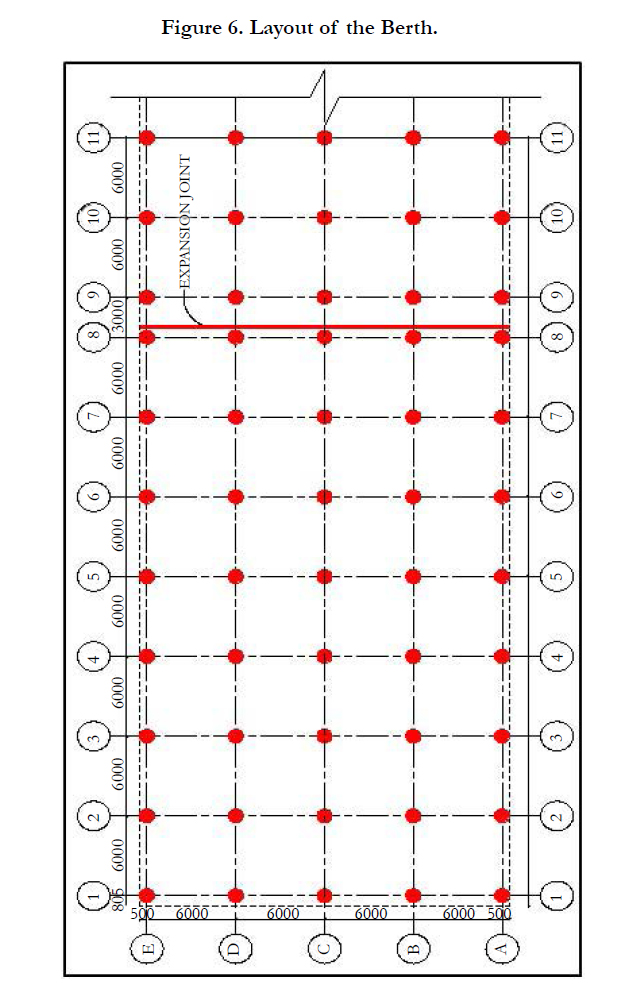
Figure 6. Layout of the Berth.
Design Berthing Force on Bulk Carriers
In order to obtain design berthing force on wharf as per different fender systems considered, design berthing energy is calculated first as per Indian Standard and British Standard. Approach velocity of vessels as per Indian Standard and British Standard are correlated for five metocean conditions and compared. Using energy-reaction curve provided by fender system manufacturer, berthing energy is converted into berthing force assuming magnitude of deflection in fender system. For different vessel sizes, design berthing energy calculated and design berthing reaction obtained as per Indian Standard and British Standard, for different fender systems along with five metocean conditions are shown from Table5 to Table 14.
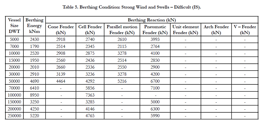
Table 5. Berthing Condition: Strong Wind and Swells – Difficult (IS).
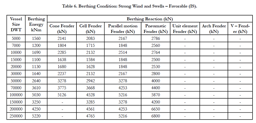
Table 6. Berthing Condition: Strong Wind and Swells – Favorable (IS).
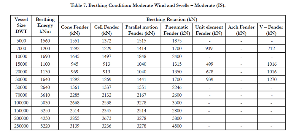
Table 7. Berthing Condition: Moderate Wind and Swells – Moderate (IS).
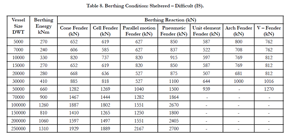
Table 8. Berthing Condition: Sheltered – Difficult (IS).
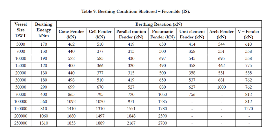
Table 9. Berthing Condition: Sheltered – Favorable (IS).
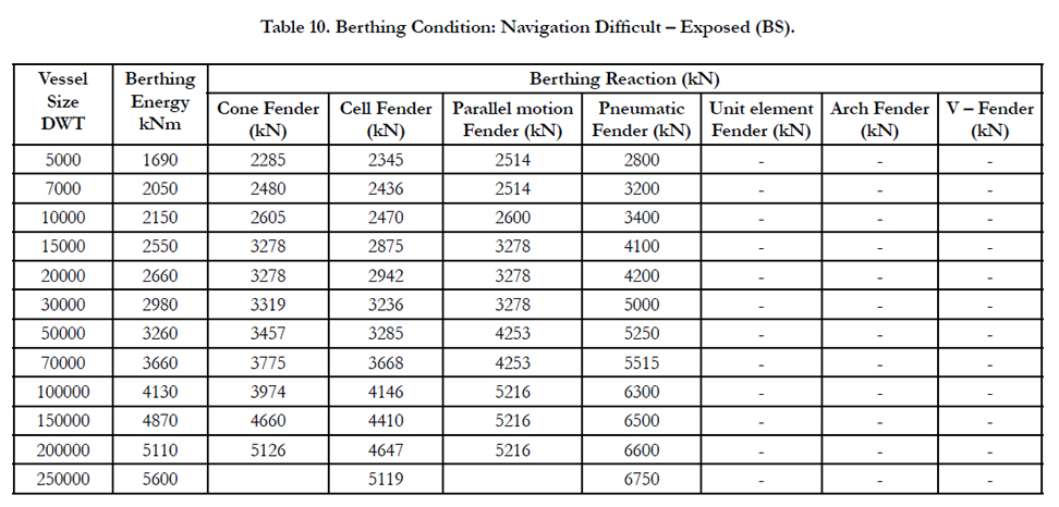
Table 10. Berthing Condition: Navigation Difficult – Exposed (BS).
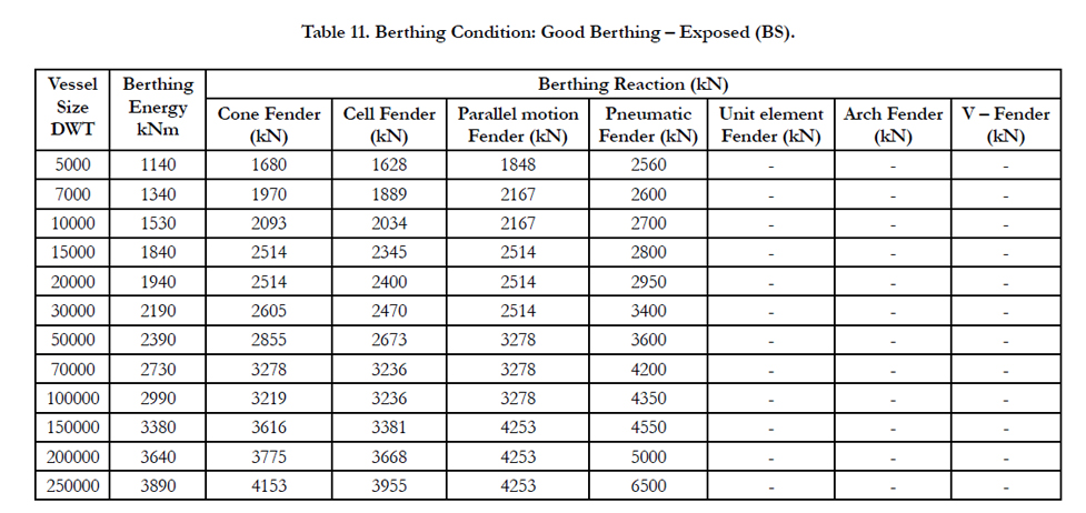
Table 11. Berthing Condition: Good Berthing – Exposed (BS).
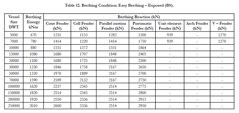
Table 12. Berthing Condition: Easy Berthing – Exposed (BS).
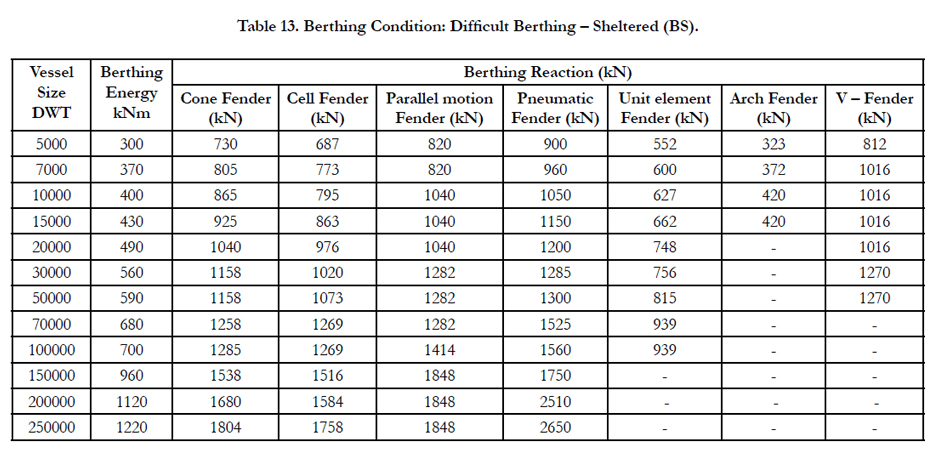
Table 13. Berthing Condition: Difficult Berthing – Sheltered (BS).
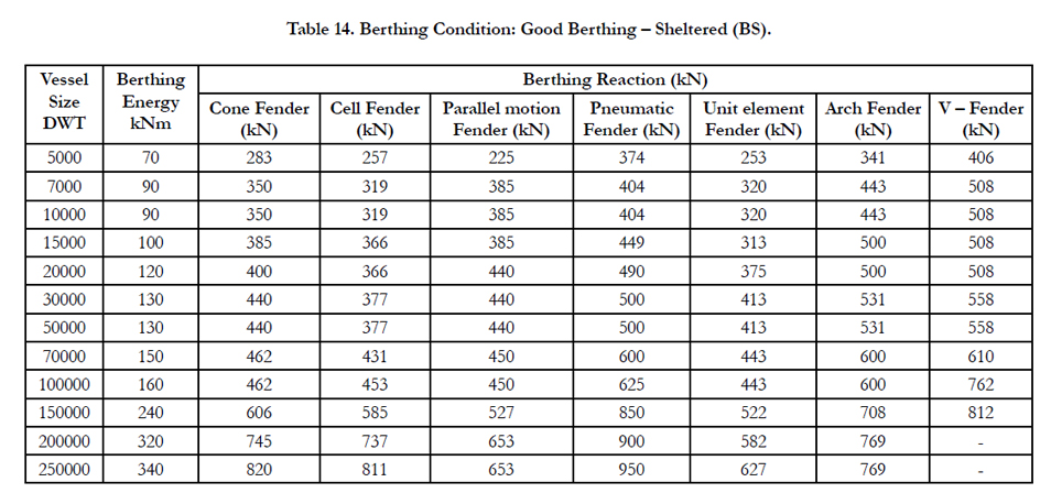
Table 14. Berthing Condition: Good Berthing – Sheltered (BS).
Post Analysis Result
Post analysis of wharf includes comparison of limit state of service ability and limit state of collapse criteria for different types of fender systems. Limit state of service ability comprises of deflection incritical pile at pile-deck junction. Limit state of collapse comprises of axial force and moments in critical pile.
Deflection in critical pile is obtained for different fender systems with five metocean conditions, and compared as per Indian Standard and British Standard, as shown from Table 15 to Table 19.
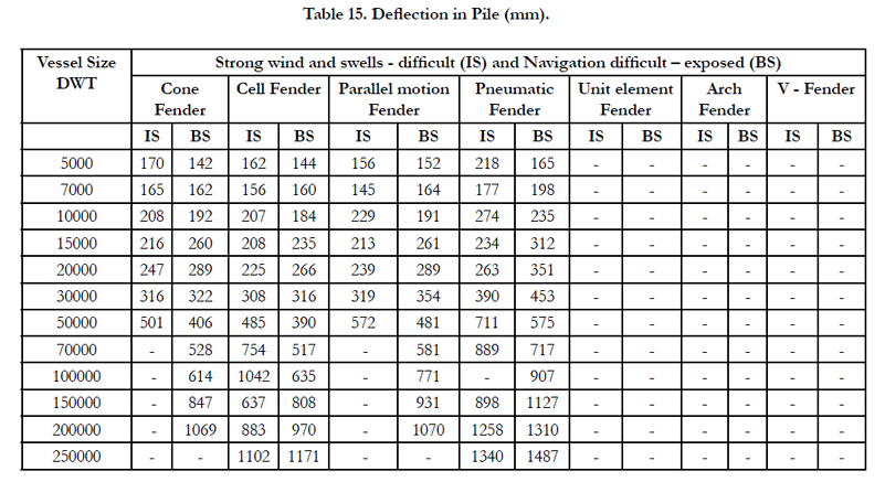
Table 15. Deflection in Pile (mm).
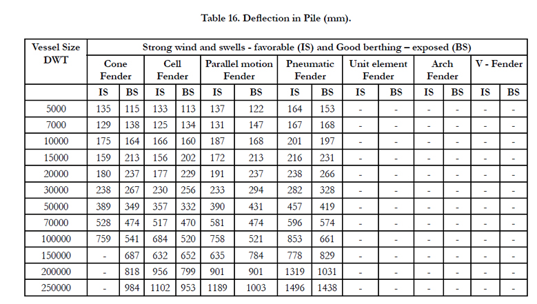
Table 16. Deflection in Pile (mm).
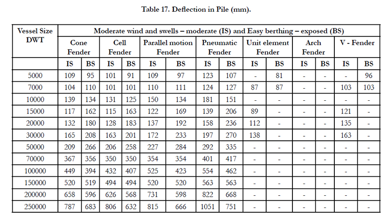
Table 17. Deflection in Pile (mm).
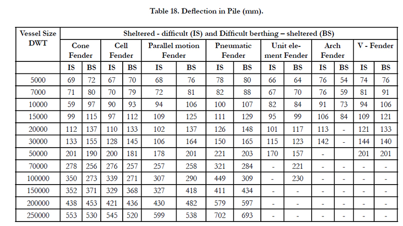
Table 18. Deflection in Pile (mm).
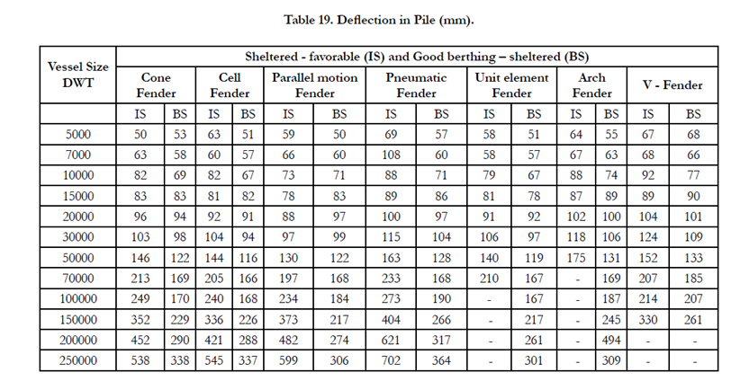
Table 19. Deflection in Pile (mm).
Axial force in critical pile is obtained for different fender systems with five metocean conditions, and compared as per Indian Standard and British Standard, as shown from Table 20 to Table24.
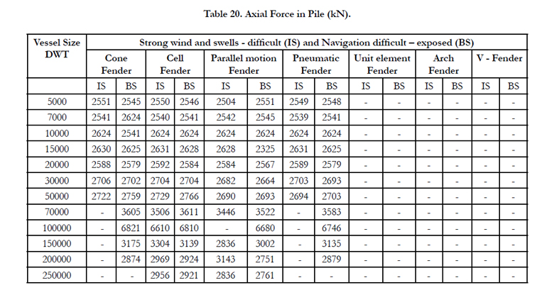
Table 20. Axial Force in Pile (kN).
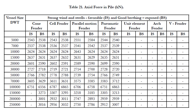
Table 21. Axial Force in Pile (kN).
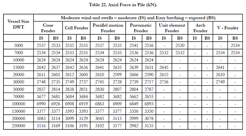
Table 22. Axial Force in Pile (kN).
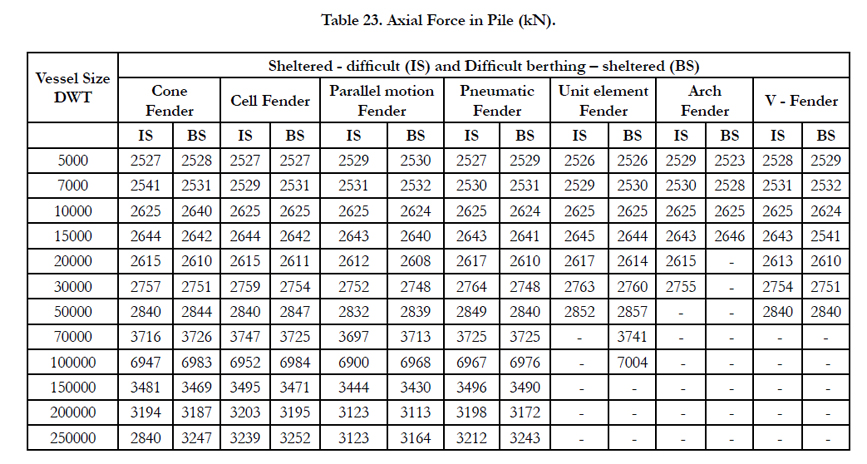
Table 23. Axial Force in Pile (kN).
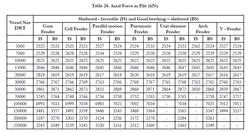
Table 24. Axial Force in Pile (kN).
Moment in critical pile is obtained for different fender systems with five metocean conditions, and compared as per Indian Standard and British Standard, as shown from Table 25 to Table 29.
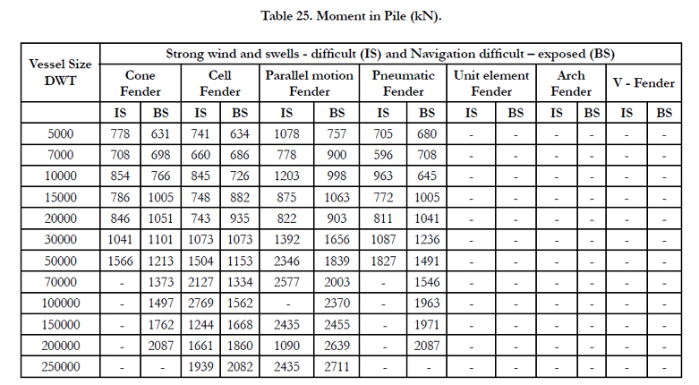
Table 25. Moment in Pile (kN).
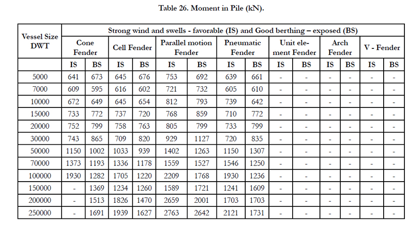
Table 26. Moment in Pile (kN).
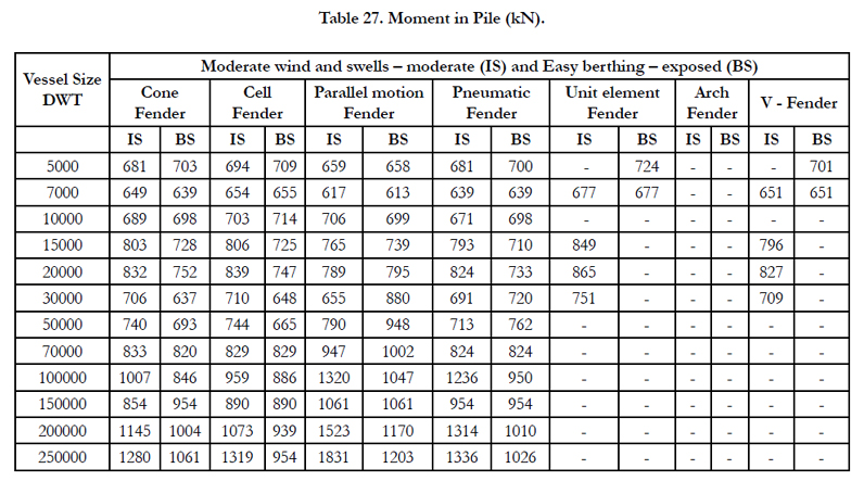
Table 27. Moment in Pile (kN).
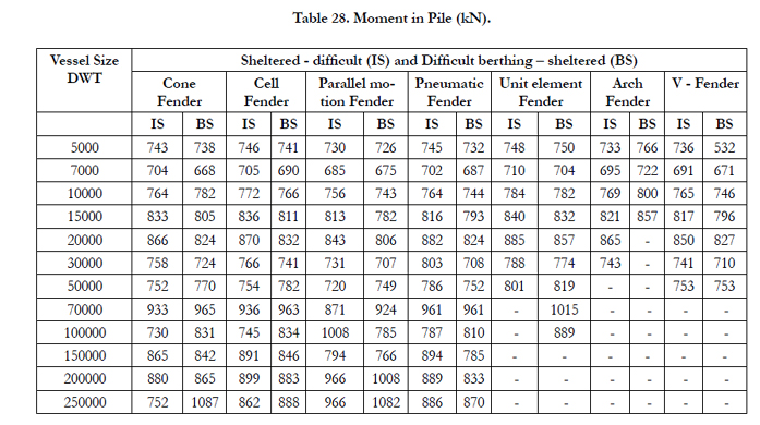
Table 28. Moment in Pile (kN).
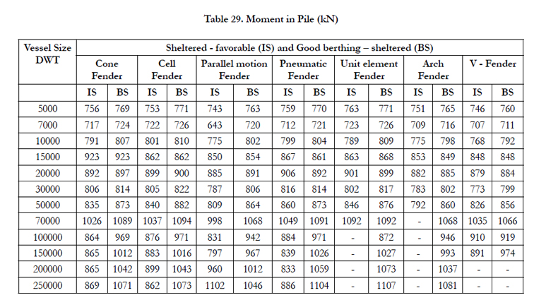
Table 29. Moment in Pile (kN)
Results and Discussions
- It is observed that British Standard gives more precise values for design berthing velocities. Moreover, Indian standard provides constant value of berthing velocity for vessel sizes more than 250000 DWT, which is not the case with British standard.
- For all metocean conditions and different fender types, British Standard provides higher values of moment in critical pile. Hence British standard governs.
- For all metocean conditions and different fender types, British Standard and Indian Standard provide almost similar value of axial force in critical pile.
- For all metocean conditions and different fender types, Indian Standard provides higher values of deflection in critical pile.
- As per limit state of serviceability, Indian Standard governs the design of the wharf.
- As per limit state of collapse, British Standard governs the design of the wharf.
Conclusions
Suitability matrix to prioritize fender system for all vessel sizes and metocean condition as per IS and BSare shown from Figure 7 to Figure 16.
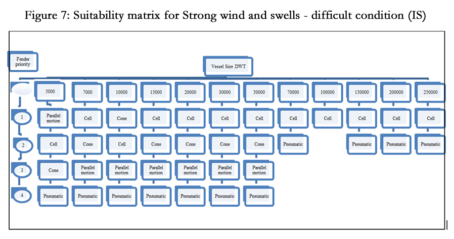
Figure 7. Suitability Matrix for Strong Wind and Swells - difficult Condition (IS).
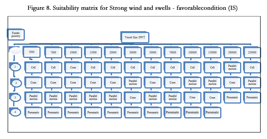
Figure 8. Suitability Matrix for Strong Wind and Swells - Favorable Condition (IS).
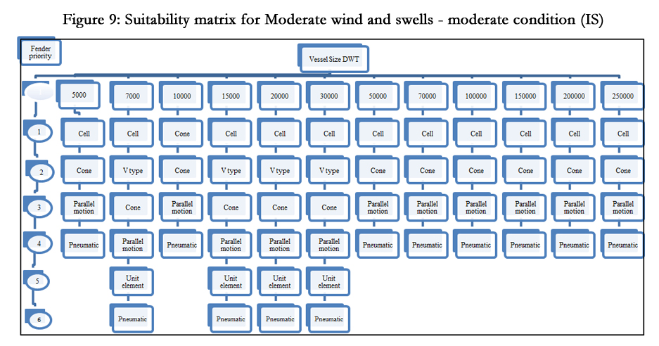
Figure 9. Suitability Matrix for Moderate Wind and Swells - Moderate Condition (IS)
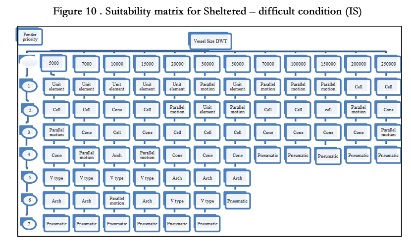
Figure 10. Suitability Matrix for Sheltered – Difficult Condition (IS).
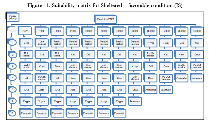
Figure 11. Suitability Matrix for Sheltered – Favorable Condition (IS).
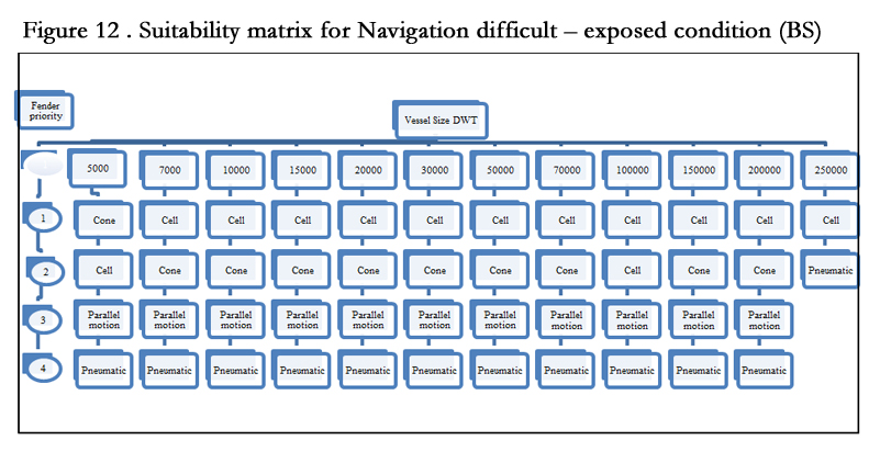
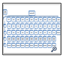
Figure 12. Suitability Matrix for Navigationdifficult – Exposed Condition (BS).
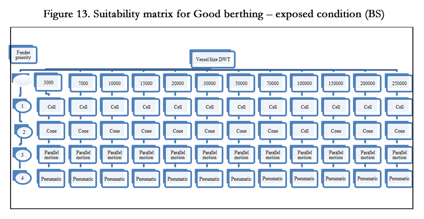
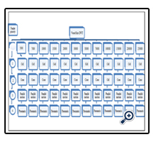
Figure 13. Suitability Matrix for Good Berthing – Exposed Condition (BS).
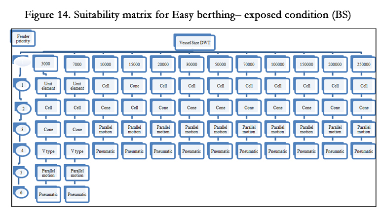
Figure 14. Suitability Matrix for Easyberthing– Exposed Condition (BS).
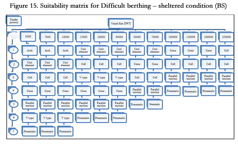
Figure 15. Suitability Matrix for Difficult Berthing – Sheltered Condition (BS).
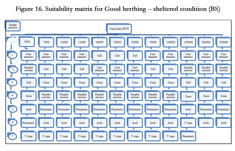
Figure 16. Suitability Matrix for Good Berthing – Sheltered Condition (BS).
References
- BS6439 part-4 (1994) Maritime structures: Code of practice for design of fendering and mooring systems. BSI, London, UK.
- Coastal Engineering Research Center (1984) Shore Protection manual Vol. II. Wahington DC: US Army Corps of Engineers.
- GMB (2014) Port sector outline - Glimpse of Gujarat. Gandhinagar: Gujarat Maritime Board.
- IRC6 (2010) Standard specifications and code of practice for road bridges. Section II. Loads and stresses. New Delhi: INDIAN ROADS CONGRESS.
- IS1786 (2008) High Strength Deformed Steel Bars and Wires for Concrete Reinforcement – Specification. New Delhi: Bureau of Indian Standards.
- IS1893 (1984) Criteria for Earthquake Resistant Design of Structures. New Delh: Bureau of Indian Standards.
- IS1893 part-1 (2002) Criteria for Earthquake Resistant Design of Structures: Part 1 General provisions and Buildings. Delhi: Bureau of Indian standards.
- IS2911 Part -1/Sec-2 (1979) Code of practice for design and construction of pile foundations – Bored cast in situ piles. New Delhi: Bureau of Indian Standards.
- IS456 (2000) Plain and Reinforced Concrete – Code of Practice. New Delhi: Bureau of Indian Standards.
- IS4651 Part- 4 (1989) Code of practice for planning and design of ports and harbours – General design considerations. New Delhi: Bureau of Indian Standards.
- IS4651 Part-3 (1974) Code of practice for planning and design of ports and harbours – Loading. New Delhi: Bureau of Indian Standards.
- PIANC (2002) Guidelines for the Design of Fender Systems, Marcom report of WG 33. Brussels, Belgium: International Navigation Association.
- TERMPOL (2010) Enbridge northern gateway project, section 3.13 - Berth procedures and provisions. Northern gateway pipelines Inc.
- Trelleborg (2002) Marine fenders. Dubai, UAE: Trelleborg Marine Systems FZE.


