Coupled Chemical Reactions in Dynamic Nanometric Confinement: VIII. Capacitive Discharges in Nuclear Track-Based Biosensing
D Fink1,2 *, J Vacik2, V Hnatowicz2, S Cruz3, G Muñoz H3, H García Arellano4, A Kiv5, L Alfonta6, AT Mansharipova7, RI Muhamediev7
1 Departamento de Procesos y Tecnologia Division de Ciencias Naturales e Ingineria, Universidad Autónoma Metropolitana-Cuajimalpa, Pedro Antonio de los Santos Col. Sn. Miguel Chapultepec, D.F. México.
2 Nuclear Physics Institute, ASCR, Řež, Czech Republic.
3 Departamento de Fisica, Universidad Autónoma Metropolitana-Iztapalapa, D.F., México.
4 Departamento de Ciencias Ambientales, División de Ciencias Biológicas y de la Salud, Universidad Autónoma Metropolitana-Lerma, Av. de las Garzas
Col. El Panteón, Lerma de Villada, Municipio de Lerma, Estado de México.
5 Department of Materials Engineering, Ben-Gurion University of the Negev, Beer-Sheva, Israel.
6 Avram and Stella Goldstein-Goren Department of Biotechnology Engineering, Ben-Gurion University of the Negev, Beer-Sheva, Israel.
7 Kazakh-Russian Medical University, Kazakhstan.
*Corresponding Author
Dietmar Fink,
Division de Ciencias Naturales e Ingineria,
Universidad Autónoma Metropolitana-Cuajimalpa, Pedro Antonio de los Santos 84, Col. Sn. Miguel Chapultepec,
C.P.11850, México, D.F.;México.
Tel/Fax: 00493080496233
E-mail: fink@xanum.uam.mx
Received: October 27, 2016; Accepted: November 28, 2016; Published: November 30, 2016
Citation: D Fink, J Vacik, V Hnatowicz, S Cruz, G Muñoz H, et al., (2016) Coupled Chemical Reactions in Dynamic Nanometric Confinement: VIII. Capacitive Discharges in Nuclear Track-Based Biosensing. Int J Bioanal Methods Bioequival Stud. 3(2), 62-75. doi: dx.doi.org/10.19070/2470-4490-160008
Copyright: D Fink© 2016. This is an open-access article distributed under the terms of the Creative Commons Attribution License, which permits unrestricted use, distribution and reproduction in any medium, provided the original author and source are credited.
Abstract
The historical capacitor concept is applied here to form polymeric swift heavy ion track-based pulsed biosensors. Due to the accumulation of charged enzymatic reaction products over a given time and their sudden pulse-wise release the sensors may obtain a detection sensitivity that exceeds that of earlier constant-current sensors by far.
1.1.The Classical Capacitor
1.2.Track-Based Capacitors for Ionic Charge Accumulation
1.3.The Different Construction Principles of Track-Based Capacitors
1.4.Etched Ion Tracks with Membranes for Biosensing: The Enzyme Location
2.First Experimental Tests
2.1.Dimensioning of Track-Based Pulsed Signal-Amplifying Biosensing Capacitor Foils
2.2.First Tests with Polymer Foils with Non-Transparent Etched Tracks
2.3.Foils with Semi-Closed Etched Tracks in Polymer Foils, Immersed in Pure Water
2.4.Comparison of Charge-Accumulating Properties of Differently Prepared Polymer Foils
3.Biosensing with Polymer Foils with Semi-Closed Etched Tracks
3.1.Biosensing with Enzyme-Free Foils Embedded in Enzyme/ Analyte Mixture
3.2.Biosensing with Enzyme-Clad Tracks in Foils, In Contact with Analyte Solution
4.Conclusions and Outlook
4.1.Possible Further Technological Developments: Tempos Biosensors
4.2.Possible Future Applications
5.Acknowledgements
6.References
Introduction: Theoretical Considerations
It took quite a time after the independent discoveries of the Leyden jars - the forerunners of our capacitors - in 1745 by Ewald J.G. von Kleist in Pomerania and in 1746 by Pieter van Musschenbroek in Holland, that the capacitor's behaviour upon application of an alternating voltage was understood. As contemporary textbooks reveal, the current I flowing through a capacitor is given by the derivative of the applied voltage U, times the capacitor's capacity C:
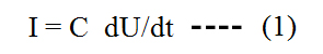
This means, the larger the change of the applied voltage, the larger the current. Consequently the maximum possible current height is given by abrupt voltage changes such as found in the case of alternating rectangular voltage:
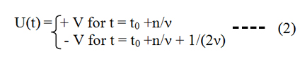
with V being the applied voltage, ν being the frequency of the voltage changes, t0 being an arbitrary starting time and n = 0, 1, 2, ... being an integer number. The corresponding current response has the shape
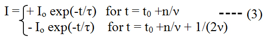
with I0 being the maximum current and τ = Rc C being the time constant of the considered system (with capacity C) which is required to discharge (i.e. to equilibrate) the stored capacitor charge via a resistance Rc. The half life time of the exponentially decaying current pulse (i.e., when half of the capacitor is discharged) is given by: tpulse = 0.69 τ .
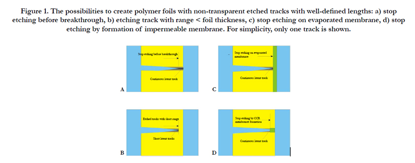
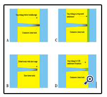
Figure 1. The possibilities to create polymer foils with non-transparent etched tracks with well-defined lengths: a) stop etching before breakthrough, b) etching track with range < foil thickness, c) stop etching on evaporated membrane, d) stop etching by formation of impermeable membrane. For simplicity, only one track is shown.
Traditional capacitors (see Figure 2a) refer to metal plates for the storage of electrons as charge carriers, being separated from each other by a dielectric layer, and to metallic wires serving for thecharge transport from the voltage source to the capacitor, or for discharging the latter. If one replaces now the metal plates by an electrolyte (hence the electrons by ions) and the dielectric layer by some impermeable foil of any material with semi-closed pores, then the same considerations hold as above. Such a porous foil material can be e.g., a polymeric foil (of typically ~ 10 to 30 μm thickness) which is known to have some intrinsic free volume - typically a few vol% - in the form of thermally fluctuating voids. If this polymer foil is irradiated by swift heavy ions (SHI), additional free volume of nanometric dimensions is created within the radiation-damaged zones: the so-called latent tracks. Simultaneously the shock wave initiated by the SHI pulse transfer to the foil leads to some polymer's compactation, i.e., to a reduction of the free volume. Depending on the specific polymer and the ion type, either the formation of excessive free volume or the compactation will dominate. Finally, when subjecting such SHI-irradiated foils to etching, large pores emerge (the so-called etched tracks) that can obtain radii of some nm up to several μm, depending on the etching time.
It is expected that the transition from pristine polymers via polymers with latent SHI tracks to polymers with etched tracks (which exhibits increasing overall free polymeric volume), will also increase the material's charge storing capability. The latter will, however, rapidly vanish if the pores become transparent as then the charges stored in the tracks will become mobile and annihilate with their counter-charges on the opposite foil side. In the case of SHI-irradiated polymer foils this can happen if e.g., one etches the tracks from one side up to the other side so that the etch cone tips open towards the opposite foil surface (etchant breakthrough). If, however, this track breakthrough is prevented, then the charge storing facility of that foil persists. There are several possibilities how to accomplish this, Figure 1:
a) One can simply stop the SHI track etching slightly before etchant breakthrough would occur. Thus, the remaining unetched polymer layers will prevent charge equilibration between both sides so that the foil's capacitive properties are preserved. However, one has to take into account that, due to some inevitable local variations of the etching speed, there exists some distribution of the etched track lengths that might lead to an early breakthrough of some of the tracks, whereas others have by far not yet reached the desired length.
b) One can adjust the energy of the impinging SHIs to a value that their ranges R in the polymer are just slightly below the foil thickness d: R<d. Then track etching for whatever time will create nanopores with lengths just slightly shorter than R (note that, due to the reduced ion stopping power near the end of the SHI trajectories, etching will not take place exactly at R any longer). However, also in this case some variations of the etched track lengths are inevitable, which stems from both the range straggling of the implanted ions and the variation in the individual track etching efficiency. In all cases, one also must take into account that the polymer foil itself suffers some reduction of its thickness by the etching.
c) One can use SHI-irradiated polymer foils onto which some thin (typically ~ 5 nm thickness) quartz (SiO2), polyethylene (PE), Ge, Cu, Ni, etc. film was evaporated before track etching. Then the evaporated layer will prevent the complete track opening. Whereas the quartz films were found to be nicely impermeable for both inorganic ions (such as H+ or OH-) and organic ions (such as {gluconic acid}-, GA-), the tracks covered by thin PE films still seem to show some moderate diffusional permeability for both the protons and the biomolecules at the PE side. Consequently, the maximum charge storage capacity will be reduced here as compared with the SiO2 - coated foils, thus worsening the corresponding sensor's performance.
d) One can produce thin track-closing membranes on foil surfaces also by means of specifically Coupled Chemical-topological Reactions (CCR) [1] during the track etching from one foil side only, so that the membranes of Ag2O [1], LiF [2], BaF2 or other CCR products emerge at the etched track tips only. If the etching continues, the radial track expansion will lead to some leakage at the membrane's outer rim which initiates again CCR, to repair the membranes and to re-establish their impermeability. Examinations by Ion Transmission Spectrometry indicated that the thickness of the thus formed membranes can be that small as ~0.2 to 0.5 μm [3].
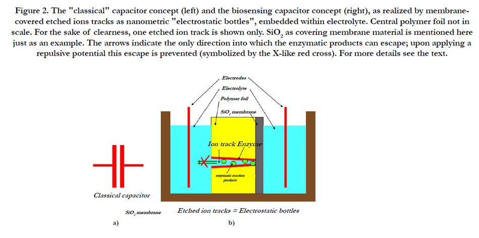
Figure 2. The "classical" capacitor concept (left) and the biosensing capacitor concept (right), as realized by membranecovered etched ions tracks as nanometric "electrostatic bottles", embedded within electrolyte. Central polymer foil not in scale. For the sake of clearness, one etched ion track is shown only. SiO2 as covering membrane material is mentioned here just as an example. The arrows indicate the only direction into which the enzymatic products can escape; upon applying a repulsive potential this escape is prevented (symbolized by the X-like red cross). For more details see the text.
Instead of forming the membranes on the foil surface within the etched track tips by e.g. the CCR strategy, they can also be localized in any other regions within the polymer foils along the etched tracks. Depending on the required membrane material, this can be done in either one step only, or it has to be done in a sequential two-step process. Let us consider an example for the first case: Suppose that track etching takes place from one foil side with a mixed NaOH/NaF solution, whereas the other foil side is immersed into a NaOH/LiCl solution. Then, track etching occurs from both sides until both etched track cones (or, more precisely according to Apel et al., [4]: etched funnel-type pores) meet somewhere in the foil center. In the moment of this etched track breakthrough the Li+ ions will react with the F- ions to form insoluble LiF membranes between the two etch cones [2].
It is impossible to apply this recipe also for Ag2O membrane formation as the preparation of a NaOH/AgNO3 solution would already lead to immediate AgOH precipitation before any track etching starts. Therefore one has to etch the tracks from both sides in a first step by NaOH only, and stop the etching process shortly before etched track breakthrough would occur. In a second step, etching is continued with NaOH from one track side only, whereas the other etched track cone is filled with pure AgNO3 solution after careful removal of the previous etchant from that side. In the moment when the etchant reaches the AgNO3-filled tracks, the CCR will lead to AgOH formation that transforms subsequently to Ag2O. The forming AgO membranes being impermeable and insulating, they will block the tracks efficiently.
As compared with etched track structures with surface membranes where the original etched tracks were transformed into bottle-like structures, we can consider etched track structures with central membranes as systems with two "bottles" adjacent to each other at their bases, within one track each. In each track, the two "bottles" are counter-directed against each other and each of them contains only half the full track volume.
Etched tracks with central membranes that were formed by theCCR mechanism have recently been studied by us thoroughly, as well theoretically [1] as experimentally. Membranes of Ag2O [1,5], LiF [2, 3], BaF2, Ca(OH)2, Ba(OH)2, CaCO3 and BaCO3 (yet unpublished) have been produced and characterized electronically [6]. If the track walls of such structures with central membranes are covered with the same enzyme on both sides, biosensors emerge that obey a different sensing mechanism than those ones made of continuous transparent tracks [7]. Also biosensors combining two different sensing properties can be constructed in this way.
Let us assume that we have a polymeric foil with membranecovered etched tracks according to Figures 1c or d. Then two geometrical arrangements are possible for the location of the enzymes that are required to initiate the selective biosensing reactions:
a) The enzymes can be simply mixed with the analyte solution to which the biosensing foil is exposed with its open etched track sides. Then an attractive voltage behind the membrane layer will first drag the charged reaction products out of the solution into the etched tracks and then keep them there just like in miniaturized bottles, so that they gradually accumulate (for simplicity, let us assume here that both the enzymes and the analyte molecules themselves are not ionized in solution, such as it is given in the case of glucose sensing by the enzyme glucose oxidase, GOx).
b) Alternatively, the enzymes can be bond to the etched track walls, so that the enzymatic reactions take place exclusively within the tracks (Figure 2b).
The essential difference between both approaches is that the first sensor type will react somewhat slower than the second one as an additional time is required for the products to migrate under the influence of the external electric field from the electrolyte into the tracks up to the thin SiO2 membrane to accumulate there - and vice versa upon reversal of the applied voltage. Furthermore, the enzyme consumption of the first sensor is, of course, much larger than in the second case.
In the second concept, enzymes (such as GOx for the case of glucose sensors) are bonded to the inner walls of etched tracks in a polymer foil or SiO2 layer by means of some chemical bridge that couples an enzyme's amino groups to the polymer's carboxyl groups (in the case of polyethylene terephthalate, PET or polycarbonate, PC) or imide groups (in the case of polyimide, PI) or the Si-O- dangling bonds in the case of SiO2 substrates. In the presence of a suitable analyte, the bonded enzyme decomposes the latter to products that are gradually enriched in the confinement of narrow etched tracks. Let us further assume that one of the track openings is now sealed by a thin impermeable and insulating layer such as shown in Figure 2b, to enhance that confinement.
To understand better what is new with this condenser-type biosensor concept, let us compare it with previous nuclear trackbased concepts. Several strategies had been developed that were denoted by us for easy distinguishing as: the charge transfer [9, 10], pore blocking [11, 12], polymeric electrolyte [13], Clarc sensor [14], product enrichment [15-17], latent track blocking [19], track gating [20] and central membrane [5, 7] concepts (for a more detailed overview see Ref. [21] and the references therein). The work of our group centered previously essentially on the "product enrichment" concept. In this case enzymes are bond covalently to the walls of long, narrow etched tracks within thin polymeric foils, so that any corresponding (preferentially neutral) analyte entering these tracks would react with the enzyme to form the corresponding charged enzymatic reaction products. The feasibility of this strategy is restricted to cases where the charge states of both the analyte and the enzymatic reaction products differ, so that a detectable change of etched track conductivity can be measured. The latter is used as the measuring parameter to probe the analyte´s concentration.
The higher the product´s concentration CF is, the better should be their detection sensitivity. Therefore it was our aim from the beginning to enrich the products F as much as possible. However, within a given transparent nanopore (such as an etched track) their production yield is always counteracted by their diffusional losses through the track openings on both sides towards the surrounding medium. Diffusional simulations performed in a recent work [22] on this question indicated that for cylindrical tracks the product concentration scales (as expected) with the analyte's (E) concentration, the square of the track length, and also roughly reciprocally with the track radius, if the latter is sufficiently small. This estimation was based on the assumption of purely diffusive behaviour within the track sensors, thus neglecting any electrofluidic effects (that stem from Coulombic interactions within narrow tracks). Though this assumption is in general not valid for etched tracks with nanometric radii, it is justified for the specific case of track-based biosensors under consideration here, as the covalent bonding of the enzymes to the track walls largely neutralizes the previous negative track wall charges, thus annihilating any electrofluidic effect here.
If one of the open sides of a cylindrical track is closed by a thin impermeable and insulating membrane - let us say, be e.g. a thin evaporated SiO2 film, then the product´s loss across the track openings will be reduced by a factor 2. Simultaneously the product concentration will increase roughly by a factor 4, as the distance from the region of maximum product concentration (here: in front of the membrane; for transparent tracks: in the track center) up to the open surface is now twice that long, and as diffusive losses scale inversely with the square of distance. As the result, we will now have a gain in detection sensitivity by roughly an order of magnitude. Distortions of the assumed cylindrical track shapes (e.g. by conically etched tracks) may worsen the result somewhat, but nevertheless substantial gains are also expected here.
The sensitivity of the biosensors can be improved further if one also suppresses the diffusional losses of the products through the remaining track openings completely. As we restrict in our biosensing concept to charged enzymatic reaction products only, this is easily possible by putting an attractive voltage behind the insulating and impermeable thin membrane. This voltage forces the ionized products to stay within the etched tracks and inhibits their escape, so that they accumulate. In the ideal case, these "electrostatic bottles" should not exhibit any loss of the products, and hence their conductivity should be zero as long as a constant (or low-frequency) voltage is applied across the foil.
However, when applying high frequency alternating voltages, capacitive currents should emerge from these biosensing capacitors. In order to optimize the current amplitudes in such a case, one should make use of sharp rectangular voltage pulses as was mentioned above in the Introduction. As the externally applied voltage acts on all etched tracks simultaneously, the stored charges in all parallel tracks are released synchroneously in one big current pulse. The current pulse height Ip will be the larger the steeper the applied voltage changes. As compared with our earlier biosensor concept of passing constant (or low frequency) currents It through transparent tracks within a given time tt (so that the total released charge is given by Qt =Ittt), this new concept with membrane- clad tracks will release the same charge Qp = Qt in a current pulse with large height Ip in a very short time, as compared to the previous constant-current biosensors tp. Thus, one expects to obtain a current enhancement η by a factor tt/tp : η = Ip/It = tt/tp. In other words, the signal/noise ratio of such a capactitive pulsed sensor should also become enhanced by a factor tt/tp . For example, for tt = 1 s and tp = 1 ms, one should obtain an improvement by three orders of magnitude. As with the present track-based constant-current biosensors, minimum detectable concentrations of 10-5 to 10-10 M could be obtained (depending on the used enzyme and the examined analyte) [17], this would signify that future SHI-track-based sensors might become able to sense concentrations down to 10-8 to 10-13 M or so, respectively.
In a previous work [8], we had pointed out that there is only a limited number of ions that can be accommodated within a latent track due to their Coulombic repulsion. At that time we had calculated by a simple one-dimensional approach (i.e. assuming that the ions can line up within the track only as a linear chain, but that not two or more can exist besides each other at the same depth in the foil), that upon applying an alternating sinusoidal voltage of 5 V amplitude across a 12 μm long track and assuming an attractive track potential of -0.5 V as compared with the surrounding electrolyte, only slightly less than 600 ions can find place within such a track, for whatever frequency of the applied electric field (i.e. also at ν = 0 Hz). Let us assume that this number might be a reasonable reference estimate also for enzymatic reaction products accumulated along L = 12 μm long etched tracks, as the result of two counteracting processes: on the one hand the free volume along etched tracks of ~10 to 100 nm radius is much larger than in latent track, thus allowing for multiple deposition of small ions at the same depth, but on the other hand we deal here with biomolecular ions of large size that will hinder each other, thus allowing for much less accommodation. Under this assumption the two shorter track compartments ("bottles", with lengths L1 and L-L1) of a track with membranes in a depth L1 within the carrier foil could host up to ~600*(L1/L) and ~600*((L-L1)/L) charge carriers, respectively (which are in one compartment cations (e.g. H+) and anions (e.g., GA- for the example of glucose detectors) in the adjacent compartment). Upon inversion of the applied voltage, thus emptying the "bottles", two current pulses with heights I0*(L1/L) and I0*((L-L1)/L) from GA- and H+, respectively, will be recorded at both electrodes, thus adding up to an overall pulse of I0. This signifies that the overall pulse height should be independent from the accurate membrane position L1 of this biosensor type.
The optimum pulse height Ipulse will be obtained if the pulse contains the maximum possible charge Qcoll ~ 600 e (with e being the elemental charge), which holds for collection times tcoll, optimum ~ 600e/IF . As, according to our previous experience, IF ~ 1 nA often holds for biosensor foils with about Φ = 106 tracks/cm² or so (Φ = track density per area), we obtain for the optimum collection time tcoll, optimum a value of about 0.1 sec. In other words, an alternating rectangular applied voltage in the order of about 5 V and 10 Hz might be the best choice. If tcoll is shorter, less charges are collected and hence Ipulse is reduced. If tcoll is larger, the measured pulse height Ipulse will not increase any longer as the excessive charge carriers being produced can no longer be accommodated in the tracks due to their Coulombic repulsion, and hence are ejected from the tracks. Worse, an excessive ionic concentration in the tracks may change the pH value that much that eventually the product dissociation is reduced and the products cannot be bond electrostatically any longer and thus get lost via diffusion. Last not least, such excessive molecules might possibly get adsorbed at the track walls, thus diminishing the enzyme activity and delaying their re-emission from the tracks. Taking the above values, we can estimate the optimum capacity C of our polymeric SiO2-covered track sensor of 1 cm2 foil area to be C = Qcoll. Φ/U ~ 20 pF.
First Experimental Tests
Table 1 summarizes the experimental conditions used for the first test experiments described below. Though the SHI-irradiated foils had been prepared already several years ago, experience tells that this age does not impose any obstacle on their etching and further use (a detailed study on the effects of track aging will be published soon). We selected the glucose/GOx system due to its simplicity (only one enzymatic reaction channel with straightforward reaction kinetics with only one intermediate), cheapness and medical importance, and as a plethora of other measurements with this system are already available for easy comparison.
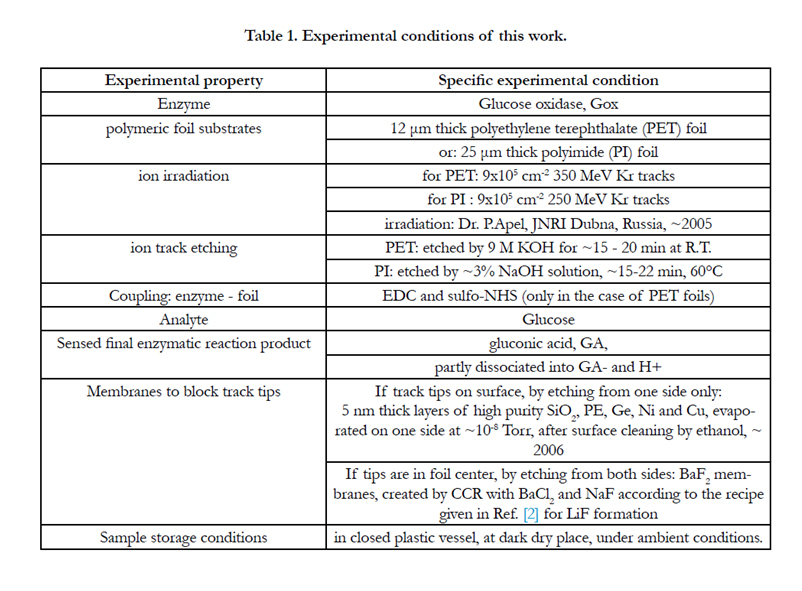

Table 1. Experimental conditions of this work.
As outlined above, the philosophy of this work is to suppress the diffusional loss of the reaction product ions from the tracks by putting an attractive electrostatic potential behind the thin insulating SiO2 membrane. In the case of a positive electrostatic potential on that side (due to a positively charged electrode behind the membrane), gluconic acid ions (GA-) will be accumulated in the etched tracks in front of the SiO2 layer, whereas the corresponding protons H+ will be repelled and ejected out of the track and thus contribute to a small reverse constant background current towards the negative counterelectrode. If that voltage is subsequently inversed, then first all previously accumulated products GA- will be ejected in a short current pulse. Thereafter the protons will be accumulated within the etched track and newly produced GA- is sent immediately to the counterelectrode.
As the total number of anions of enzymatic reaction products is the same as that of the corresponding cations, we expect that as well the positive pulses as the negative ones will have roughly the same absolute heights. Slight differences might, however, occur due to the different charge collection times of the (light, hence rapid) protons and the (much larger, hence slower) biomolecule anions. Also, we should take into account that we will always have some background signal due to the water dissociation products H+ and OH- as well as from impurities (therefore, the use of ultrapure water is strongly recommended for all such high-sensitivity measurements).
By the proper choice of both the applied voltage and the alteration frequency of the applied voltage, one has the possibility to optimize the working conditions of this biosensor. A too low applied attractive voltage across the insulating layer will not fully suppress the diffusional losses of the ionic products, thus worsening the detection efficiency. On the other hand, a too high attractive voltage would initiate current spikes through the thin sensitive membranes which either could contribute to unwanted electronic noise, or even would destroy these membranes.
If the thin evaporated layer (according to Figure 1c) on the etched track surface (that prevents the diffusional enzymatic product loss in one direction) would not be insulating but e.g. a conducting metal foil (e.g., of Cu or Ni, see Table 2), then the charged reaction products will deliver their charges to the metal foil, get neutralized and then diffuse out of the tracks without being accumulated there. This means, the current pulse formation (which is the essential part of this biosensor concept) will not take place; hence such a design were useless.
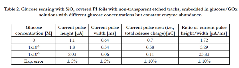
Table 2. Glucose sensing with SiO2 covered PI foils with non-transparent etched tracks, embedded in glucose/GOx solutions with different glucose concentrations but constant enzyme abundance.
The PE and PI foils irradiated with swift heavy ions and covered with SiO2, PE, Cu or Ni membranes were etched on their nonevaporated sides as described in Table 2.
Etching the PI foils for test purpose with ~10% NaOCl at 80°C and applying 1V, as well at low (0.5 Hz) as at high frequency (~1 kHz) always resulted in either membrane destruction or flaking, the latter being visible even by the naked eye due to a change in surface reflectivity. To prevent this, we had to reduce the etching speed by more than one order of magnitude, by etching with only 3% NaOCl at ~ 60°C for ~15 - 22 min and applying a test voltage of only 0.1 V amplitude at ~0.5 Hz. This yielded the desired result insofar as the evaporated membranes survived the track etching, and no more catastrophic breakthrough occurred.
Concerning PET foils with evaporated SiO2, (or PE, Cu or Ni) membranes, we hardly had such problems: during track etching the low-frequency current signal of SiO2-coated foils always remained near-zero indicating that the SiO2 membranes were stable (and thus suppressed Ohmic currents efficiently). The corresponding high-frequency current strongly increased up to some saturation value, due to the high capacity stemming from both the polymer film with its high dielectric coefficient and the evaporated SiO2 membrane with its very narrow thickness.
Below, as a first feasibility test, we will first show with sensor foils embedded into water that the application of rectangular voltage pulses to foils with membrane-covered etched tracks does indeed lead to the expected current pulses. Subsequently we compare the charge-accumulating properties of pristine polymer foils, c nonetched SHI-irradiated foils and SHI-irradiated foils with (partially or fully) etched tracks with each other in pure water. In a next step we will show that enzyme-free polymer foils with etched tracks clad by membranes react on enzyme/analyte mixtures, and finally we will present the first result of a membrane-clad biosensor with enzymes bond to the etched track walls.
For the first feasibility tests of this concept, these structures were immersed in double deionized water on both sides. This means, we restrict here to the smallest and most mobile ion type H+ (and of course their counterions OH-). Therefore, the results obtained here partly do not directly apply also for the larger biomolecular ions under consideration here (such as {gluconic acid}- or others), as these ions will not be able to enter into the very tiny free volume areas of pristine or non-etched irradiated polymers. Anyhow, this study gives an important clue for the ionic dynamics in such a system and is important for the estimation of the inevitable measuring background.
Upon applying an alternating rectangular voltage of ± 5V at frequencies in the ~0.1 Hz to 1 kHz range, indeed the expected current spikes showed up, Figure 3. Their heights are in the typical order of some μA. This contrasts markedly to our previous experiments with biosensors based on transparent ion tracks (see e.g., Refs. [16-18]) where the currents were usually in the order of some ~0,01....1 nA only. It reconfirms that we encounter here indeed a remarkable improvement in the signal/noise ratio by several orders of magnitude, by accumulating charge carriers over an
extended time.
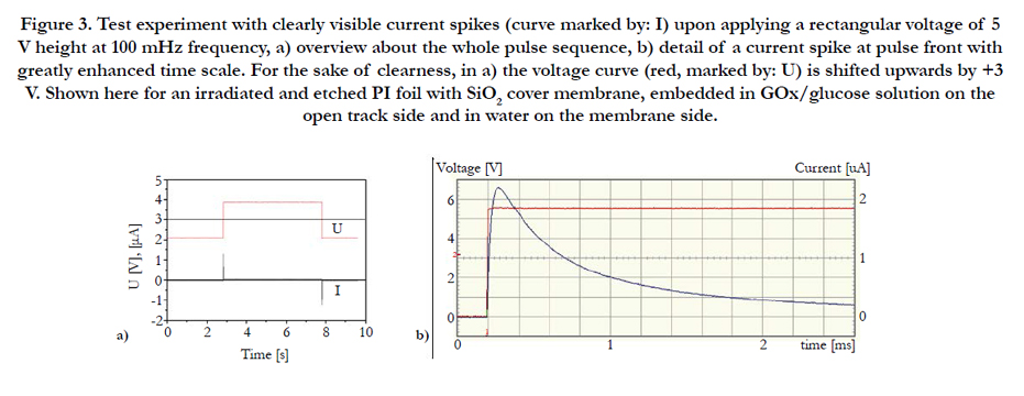
Figure 3. Test experiment with clearly visible current spikes (curve marked by: I) upon applying a rectangular voltage of 5 V height at 100 mHz frequency, a) overview about the whole pulse sequence, b) detail of a current spike at pulse front with greatly enhanced time scale. For the sake of clearness, in a) the voltage curve (red, marked by: U) is shifted upwards by +3 V. Shown here for an irradiated and etched PI foil with SiO2 cover membrane, embedded in GOx/glucose solution on the open track side and in water on the membrane side.
Figure 4 shows that there also exists a pronounced frequency dependence of the current pulse height of etched PI foils with SiO2 membrane coverage. Whereas at frequencies around 10 Hz, the current pulses are nicely stable and reproducible, this is no longer given at lower frequencies. Here, the current pulse heights decrease with decreasing frequency, though the spike widths appear to be frequency independent (hence also the totally released charges decrease with decreasing frequency). Furthermore, at very low frequencies (< 1Hz or so) the current pulses show up only sporadically, being usually well-pronounced at the beginning of the measurement cycle but decreasing thereafter until they are eventually completely missing (not shown here). This might indicate that the tightness of our track-based "electrostatic bottles" is finite, allowing for some minor leakage of the accumulated particles during some extended diffusion time.
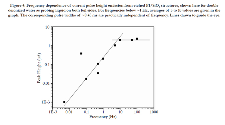
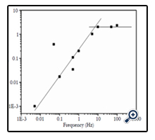
Figure 4. Frequency dependence of current pulse height emission from etched PI/SiO2 structures, shown here for double deionized water as probing liquid on both foil sides. For frequencies below ~1 Hz, averages of 5 to 10 values are given in the graph. The corresponding pulse widths of ~0.45 ms are practically independent of frequency. Lines drawn to guide the eye.
When embedding no polymer foil at all into the water-filled measuring vessel, no current pulse is found upon application of rectangular voltages (not shown here), so that instrumental artefacts can be excluded as possible sources for the effects described here. We mentioned above that every polymer should have some chargestoring (and releasing) capability due to its intrinsic free volume, and we expressed our expectation that SHI irradiation and etching of SHI tracks should increase that capability even further. This expectation is indeed verified in Figure 5 as a function of the applied frequency. The current spike heights (Figure 5a) of polymer foils with latent tracks immersed in high-purity water are indeed up to two times higher than those ones of pristine foils, probably due to both the larger overall intrinsic free volume and better connectivity of the individual free volume elements which allow for more rapid ionic migration and their accumulation at the electrodes. The current pulse heights of polymer foils with membrane-covered etched tracks exceed all others as the ionic migration along the straight etched nanopores is facilitated even more so that the charge pulses are collected and extracted faster. With increasing applied frequency for whatever sample, the current pulse heights first increase and then come to saturation or even decrease, Figure 5a, indicating that the charge collection time per period becomes too short to fill up all the miniaturized "bottles".
In all cases the pulse widths (Figure 5b) slightly decrease with increasing frequency. They are highest for pristine foils, as it takes longest to release the ions from the very small free volume elements buried deeply in the bulk material. As both the latent and the semi-closed etched tracks provide additional escape routes from the sample's interior, their accumulation times are smaller and hence is the current pulse width.
Concerning the product of pulse height and width, i.e. the totally released charge (Figure 5c), two counteracting mechanisms operate: On the one hand, SHI irradiation leads to an increase of the free volume due to the production of volatile radiochemical reaction products that degas from the polymer. Also, the better connectivity of the free volume elements along latent tracks make the latent ion tracks behave like "irrigation channels" so that the water (and hence also the charge carriers) can be easier inserted into, or extracted from the polymer.
Consequently, the current pulse height (i.e. the speed of charge extraction) increases and the pulse width (i.e. the time necessary for charge extraction) decreases in the presence of latent tracks. On the other hand, the swift heavy ion irradiation also leads to a compaction of the internal free volume by means of cross-linking and shock waves. The fact that the totally released charge decreases upon irradiation indicates that compaction effects dominate in our case.
Ion track etching adds to the available free volume and broadens these "irrigation pipes" considerably so that the speed of charge extraction (hence the current pulse height) increases even more. This is why the totally released charges increase again and happen to become at least equal in magnitude as pristine foils for samples with semi-transparent etched tracks.
Due to the close similarity of the total charge release from pristine polymers and polymers with semi-transparent etched tracks, one may conclude that the free volume of the etched tracks adds only very little to the polymer's overall intrinsic free volume. So it is essentially the ionic mobility - and not the overall number of stored ions - that leads to the larger current pulse heights and reduced pulse widths of semi-closed etched tracks in the case of H+ and OH- ions considered here. In fact, it is the impermeability of the SiO2 membranes which enables the accumulation of protons and hydroxyl ions and their later pulsewise emission.
However, the situation is expected to change strongly when going from the smallest possible ions of these test experiments to the much larger biomolecular ions, see below. As the tiny intrinsic polymer's free volume elements are no longer accessible for such large ions, the storage capacity of the pristine polymeric bulk should become near-zero for biomolecular ions, and only the etched tracks will be capable to allow for their accumulation.
Concerning the frequency dependence, the total charges released from pristine and irradiated foils differ somewhat from each other at higher frequencies (Figure 5c), which is understood as the consequence of increasing capacitive currents across the incorporated water in the irradiated (and eventually etched) polymers. Evaluating the current pulse height/width ratio, Figure 5d, all curves show the same frequency dependence. Here SHI irradiated foils exhibit the greatest change in current pulse response with increasing frequency.
The fact that the total charges (Figure 5c) of the pulses released from latent tracks are somewhat smaller than those from pristine foils or foils with semi-closed etched tracks, indicates that either the SHI irradiation has compacted the polymer’s free volume somewhat, e.g. via shock waves and/or cross-linking (thus reducing both its free volume and the free volume's easy accessibility) or that some charge carrier adsorption takes place in the irradiated foil region, or both. In fact, irradiated areas in polymers are known to be rich in radicals and metastable molecules [23].
For the sake of clearness, a detailed study was performed for the moments of etchant breakthrough of an ion-irradiated PET foil without membrane coverage, in the above-described current pulse emission mode, Figure 6. Before etchant breakthrough (stage 1) and after voltage inversion, a sharply increasing strong current pulse emerges, which shows a subsequent long tail (which is indicative for the capacitive nature of the residual unetched polymer part along the latent track). When approaching the breakthrough moment (stage 2), both the pulse amplitude and width still increase slightly, before that pulse collapses within a few seconds (stage 3), as the shortcut between both foil sides via the etched tracks prevents any charge carrier accumulation at all. Simultaneously the low-current region in front of the current pulses increases which is indicative for the rapidly decreasing Ohmic resistance of the track breakthrough region. Finally, after full etched track opening (stage 4), no more current pulses are found, indicating the purely Ohmic nature of that stage.
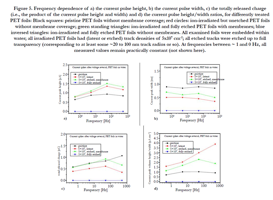
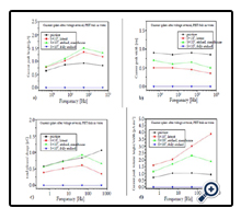
Figure 5. Frequency dependence of a) the current pulse height, b) the current pulse width, c) the totally released charge (i.e., the product of the current pulse height and width) and d) the current pulse height/width ratios, for differently treated PET foils: Black squares: pristine PET foils without membrane coverage; red circles: ion-irradiated but unetched PET foils without membrane coverage; green standing triangles: ion-irradiated and fully etched PET foils with membranes; blue inversed triangles: ion-irradiated and fully etched PET foils without membranes. All examined foils were embedded within water; all irradiated PET foils had (latent or etched) track densities of 5x107 cm-2; all etched tracks were etched up to full transparency (corresponding to at least some ~20 to 100 nm track radius or so). At frequencies between ~ 1 and 0 Hz, all measured values remain practically constant (not shown here).
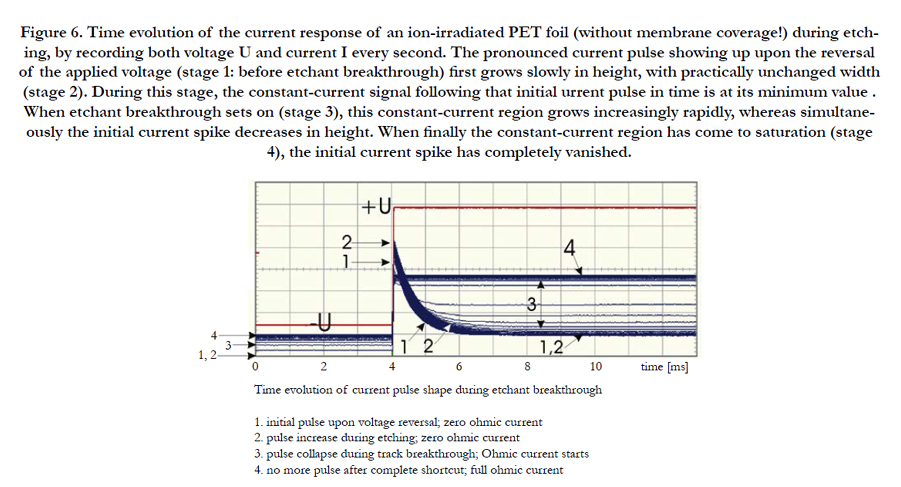
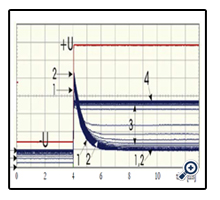
Figure 6. Time evolution of the current response of an ion-irradiated PET foil (without membrane coverage!) during etching, by recording both voltage U and current I every second. The pronounced current pulse showing up upon the reversal of the applied voltage (stage 1: before etchant breakthrough) first grows slowly in height, with practically unchanged width (stage 2). During this stage, the constant-current signal following that initial urrent pulse in time is at its minimum value . When etchant breakthrough sets on (stage 3), this constant-current region grows increasingly rapidly, whereas simultaneously the initial current spike decreases in height. When finally the constant-current region has come to saturation (stage 4), the initial current spike has completely vanished.
Biosensing with Polymer Foils with Semi-Closed Etched Tracks
We begin our examinations on biosensing with the above-mentioned Case a) of chapter 1.4, where etched track-containing PI or PE foils with evaporated SiO2 coverage on one foil surface side are exposed to mixed enzyme/analyte solutions of different concentrations.
Alternatively, we also used as-irradiated polymer foils without SiO2 coverage where we stopped the etching process slightly (~1/2 to 1 min) before the expected breakthrough would occur (as indicated by an increasing high-frequency signal of a transmitted test current), see Figure 1a. Thus, some polymer layer (of maybe 0.5 μm thickness or less) still persisted which overtook the role of the track coverage on one side. Our measurements have shown that the biosensing performance of such foils is quite similar – only slightly inferior - than that of the PET foils with evaporated SiO2 layers (Figure 1c) where all latent track material had been removed carefully. Therefore we do not report these results here separately. It appears to us that for future practical applications, the configuration according to Figure 1a is preferable, as such foils have a much better mechanical stability than those ones with the delicate evaporated thin SiO2 membranes. Here it is possible to apply relatively high test voltages (of at least 10 V) leading to high current pulses (which enable better measuring accuracy), without any risk of foil destruction.
For the first biosensing tests with the structured PI/SiO2 foils, different 50:50 vol% {GOx/glucose} solutions were prepared consisting of 0.5 mg of the enzyme glucose oxidase (GOx) per ml on the one hand, and glucose solutions of 0, 1x10⁻⁵ and 1x10⁻³ M on the other hand. These solutions were inserted into the left measuring chamber of Figure 2b (i.e., facing the open track sides), whereas the right measuring chamber was filled with double deionized water only. Table 3 and Figure 7 indicate that both the spike heights and widths correlate with the glucose concentration, i.e. that these structures really act as biosensors.
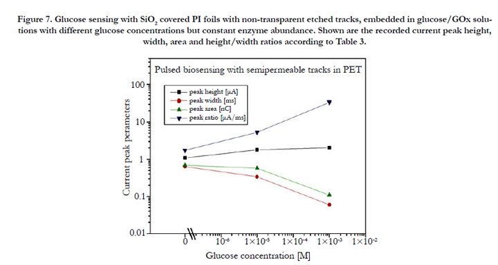
Figure 7. Glucose sensing with SiO2 covered PI foils with non-transparent etched tracks, embedded in glucose/GOx solutions with different glucose concentrations but constant enzyme abundance. Shown are the recorded current peak height, width, area and height/width ratios according to Table 3.
One finds that in this case, the current peak widths dependence on the glucose concentration exceeds that one of the peak height by far (this is interesting as the peak widths changed only marginally when exposing the various polymer foils to pure water, see above). Consequently the total amount of released enzymatic reaction products decreases with increasing concentration, whereas the peak height/width ratio increases. This amazing result indicates that the higher the analyte concentration, the less products are capable to accommodate in the tracks. We attribute this tentatively to both the spatial restriction in the narrow etched track's confinement and to the ion's Coulomb repulsion which prevents excessive charge carrier densities. In contrast to the small ions (H+, OH-) studied above, large biomolecular ions (e.g., GA-) cannot penetrate into the surrounding polymer's free volume to be stored there, so that many of them have to leak out from the etched tracks immediately after their formation. Due to that loss of stored charged reaction products, the current pulse height increases only marginally with increasing glucose concentration. (This situation might change for larger etched track diameters, which has not yet been examined).
The higher the glucose concentration, the smaller the current pulse width. This means, the GA- electro-mobility increases with their concentration. Possibly it is the product's Coulomb repulsion that facilitates their movement out of the tracks, once the external attractive potential is switched off that keeps them in the "electrostatic track bottles". The pulse width, as well as the derived pulse height/width ratio are the decisive pronounced quantities for biosensing in this case.
Note that there exists quite a high background signal even at zero glucose concentration, due to the dissociation of the carrier liquid (here: double deionized water) including its impurities. This is the sensitivity-limiting factor in measuring low analyte concentrations via such electronic signals.
As above, we also deal here with polymer foils with embedded conical etched tracks, which were covered by evaporated SiO2 membranes on their tip sides, however now these etched track are additionally covered by enzymes on their inner walls. Further, we also consider here PET foils with enzyme-clad etched tracks, where BaF2 membranes were inserted either into the track tip region or – if track etching was performed on both foil sides – into the foil centers where both etched track cones meet. Such BaF membranes were produced by the technique of Coupled Chemical Reactions (CCR) as described already above [1-3]. In the presence of BaCl2 solutions on one foil side, and of NaF/ NaOH mixtures on the other foil side, BaF2 membranes emerge at the point where the etched track cone tip meets the opposite polymer surface. If, however, some double-conical track structure was already prepared before both the BaCl2 and NaF/NaOH solutions were inserted, BaF2 membranes emerge at the meeting point of the conical tracks well within the foil center. The subsequent step is the bonding of the enzymes to the track walls. As the latter is much easier to be accomplished for PET than for PI substrates, we use in this work only ion-irradiated PET foils. Our test enzyme GOx is coupled to surface amino groups on the etched ion track walls, which had been formed after substitution of the PET’s natural surface carboxyl groups via the EDC/S-NHS strategy documented earlier [15].
First, Figure 8 summarizes the voltage calibration curves obtained with this system for embedded double distilled water. One sees that the pulse height (Figure 8a) is nicely proportional to the voltage above a threshold of ~0.2 V. The pulse widths calibration curves (Figure 8b) are less linear and show a pronounced threshold regime below ~ 1 V or so. This means, the current pulses are sharpest for voltages below ~1V. There is a remarkable constant difference of ~ 1 ms between the pulse width calibration curves for rising and falling pulses. They are tentatively attributed to the asymmetry of this sensor, as we deal where with conical tracks with membranes only on the track tip sides.
Figure 9 a,b shows the biosensor's response (as given by the recorded pulse heights and widths) on the glucose concentration for the two different sensor configurations with BaF2 surface membranes and central membranes. Whereas one foil side was exposed to glucose solution, the opposite side (in the case of the sensor with surface membranes: the track tip side) was exposed to deionized water. No major difference is seen between rising and falling pulses. Good calibration curves emerged at least from ~10-6 to 10-3 M for the pulse heights and widths; however at higher concentrations saturation effects emerge that distort the curves. Both pulse height and width are well inverse to each other. It is advantageous that the measured pulse height is larger at lower glu-cose concentrations than at larger ones, as this favours the sensing of glucose at lower concentrations. Two reasons may be responsible for the latter effect:
a) The accumulation of both the charged enzymatic reaction products and their counter-ions across the membranes leads to some intrinsic polarization which counteracts the direction of the externally applied electric probing field after its first applied half phase, and which is the stronger the larger the analyte concentration is. Thus, an increasing ionic fraction is hindered from escaping from the electrostatic bottle with increasing analyte concentration, and consequently the measured biosensor current decreases [7].
b) Another reason may be the higher mobility of the OH- and H+ ions than that one of the larger biomolecule ions, which enables better focusing in time scale upon voltage reversal.
The derived quantities: current pulse area (= product of pulse height and width) and height/width ratio are compiled in Figure 9c for both sensor configurations for easy comparison. Interestingly the curves for the pulse areas (i.e. of the products of pulse height and width) are nearly independent from the BaF2 membrane position (tip or center), and also from the glucose concentration, so that this parameter turns out to be rather useless for biosensing. The reason of this is, of course, the reciprocity of both pule heights and widths. However therefore, the height/ pulse ratios show a marked concentration dependence so that this parameter is useful for biosensing. From Figure 9c) it appears that sensors with centrally arranged membranes are slightly more sensitive than those with surface membranes.
One open point remains: Figure 9 show that good biosensing is possible only up to ~10-3 M, and that at higher concentrations the sensing tendency reverses. A possible explanation for this effect may be this one: When the high-purity water in the previous systems is replaced by a GOx/glucose solution, new charge carriers (GA- and H+) add to the previous ones (OH- and H+) in the electrolyte, so that the relative abundance of the small charge carriers (OH- and H+) decreases in favour of the larger (GA-) ones, especially for high GA- (hence glucose) concentrations. Hence, as the narrow intrinsic pores in the polymer's bulk only enable the accommodation of tiny ions there, the overall amount of stored ions decreases, which is indeed clearly illustrated in the figures. As the large charge carriers of the GA- type cannot migrate deeply into the narrow intrinsic pores, they will rather remain at the pore entrances, from where they can be released much faster than the deeply buried lighter ions, and consequently the pulse width will decrease in this case, whereas the pulse height will increase at the highest glucose concentration - which was indeed observed.
When repeating the above experiments with PET/Ni membranes (instead of SiO2 membranes) under else identical conditions, only very tiny positive current pulses could be detected after the voltage inversion, that were superposed on a comparatively very big constant current background. The corresponding negative current pulses were missing at all. This indicates that such a configuration acts rather like our previous constant-current sensors, with protons being immediately neutralized at the metal foil, and most of the enzymatic reaction products following soon thereafter - thus preventing largely the reaction product accumulation within the tracks.
Apart from the experiments reported here we also performed tests with sensors with centrally produced Ag2O membranes within etched tracks in 25 μm thick kapton foils, produced according to the recipe of Ref. [1] (not shown here). They yield quite similar results, reconfirming the above finding that the membrane position is, in principle, of secondary importance for biosensing. All comparisons of the calibration curves obtained with membranecontaining biosensors with our earlier ones using just transparent enzyme-clad etched tracks (without membranes) show nice consistency with each other, indicating that in principle, both approaches are suitable for biosensing. However, the here-reported pulsed “electrostatic bottle” technique seems to be more sensitive at lower analyte concentrations.
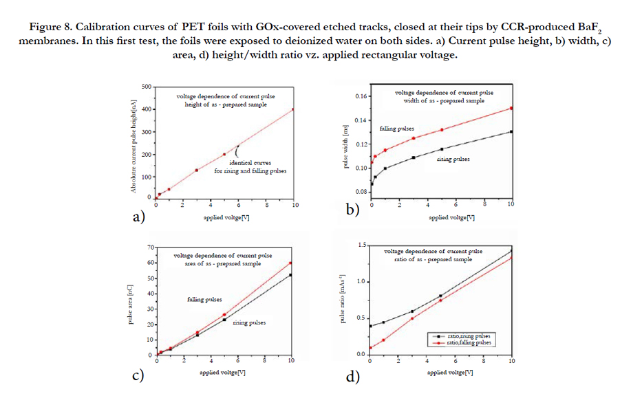
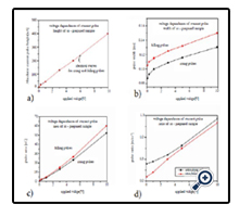
Figure 8. Calibration curves of PET foils with GOx-covered etched tracks, closed at their tips by CCR-produced BaF2 membranes. In this first test, the foils were exposed to deionized water on both sides. a) Current pulse height, b) width, c) area, d) height/width ratio vz. applied rectangular voltage.
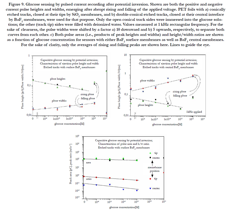

Figure 9. Glucose sensing by pulsed current recording after potential inversion. Shown are both the positive and negative current pulse heights and widths, emerging after abrupt rising and falling of the applied voltage. PET foils with a) conically etched tracks, closed at their tips by SiO2 membranes, and b) double-conical etched tracks, closed at their central interface by BaF2 membranes, were used for that purpose. Only the open conical track sides were immersed into the glucose solutions; the other (track tip) sides were filled with deionized water. Values measured at 1 kHz rectangular frequency. For the sake of clearness, the pulse widths were shifted by a factor a) 10 downward and b) 5 upwards, respectively, to separate both curves from each other. c) Both pulse areas (i.e., products of peak heights and widths) and height/width ratios are shown as a function of glucose concentration for sensors with either BaF2 surface membranes as well as BaF2 central membranes. For the sake of clarity, only the averages of rising and falling peaks are shown here. Lines to guide the eye.
Conclusions and Outlook
As a resume, we may state that the proposal presented here, to replace the previous constant-current sensor concept (for detecting enriched charged enzymatic reaction products within the confinement of etched tracks) by a pulsed-current biosensor strategy works well. The accumulation of the reaction products over a longer time and their release within a rather short time - typically fractions of a millisecond - enables one to enhance the current signal by some orders of magnitude, thus expanding the lower limits of this track-based biosensing approach. Broader etched ion tracks could improve the sensor performance further, to store more charges within each track and thus to obtain still higher pulses.
The present biosensor-pulsation concept was developed here for carrier-free thin polymer foils with either thin membranes produced by the CCR strategy or by evaporated insulating impermeable films only. Pulses with well-defined heights as obtained here make the integration into conventional electronics feasible, by just inserting an analogue-to-digital converter module in between. This holds especially for combining the present strategy with TEMPOS structures (i.e. Si/SiO2 bilayer structures with etched ion tracks in the insulating SiO2 cover layer) [24-27]. If these tracks were separated from the Si by a thin insulating membrane, they would also act as electrostatic bottles and thus enable the proposed biosensor strategy. Until now, the very thin thickness of the SiO2 layers on Si (typically 200 nm, as compared with ~12 μm of the polymer foils) made us think that these structures would not be useful for biosensing, as we had always the purely diffusional losses of the enzymatic reaction products in mind that scale with the square of the track length. However, when restricting to charged enzymatic reaction products and applying sufficiently high attractive potentials across the SiO2 membranes to control the ionized enzymatic product's mobility, this argument is no longer valid: even ion tracks as short as those of TEMPOS structures (with about typically 200 nm length only) could accumulate the reaction products without diffusional loss, if only the attractive potential would be high enough. Furthermore, the disadvantage of the short track lengths in the TEMPOS structures could be compensated by using larger etched track diameters, to obtain the same or even larger track volumes for accommodating a sufficient number of reaction product ions. In such a case, the individual current pulses initiated by abrupt potential reversals would enter into the conducting channel in the Si below the Si/ SiO2 interface, and the interaction of the different current pulses stemming from neighbouring tracks placed on slightly different potentials (if additionally applying a potential difference parallel to the SiO2 surface, as it is done in TEMPOS structures) therein should again lead to collective electronic effects such as negative differential resistances, which are useful for both intrinsic signal amplification and further data processing [24-26].
As this work is thought to be only a feasibility study for the use of swift heavy ion irradiated thin polymeric foils as condenserbased biosensors, we applied here for demonstration the glucose/ glucose oxidase system as one of the most common, simplest and cheapest biosensor systems. But of course, this strategy can and should also be expanded to other more refined and challenging biosensor problems. Specifically, we think at applying it to monitor acetylcholine (ACh) via the enzyme acetylcholine esterase (AChE), due to the importance of ACh as a neurotransmitter. Once such ACh biosensors exist, they can be used for sensing of natural venoms and toxins, and also of synthetic organophosphors such as insecticides and chemical nerve agents. Essentially in the latter cases, the advantage of the presented strategy to lower the sensing threshold is of utmost importance as such toxins may already be fatal at lowest concentrations. Vice versa, ACh/ AChE biosensors could of course also be used to monitor AChE, by inverting the sensing principle.
Another future possibility may be the direct coupling of such biosensors for essential substances to the human brain to enable shortest response times, as the pulse frequencies are in a comparable order of magnitude. This coupling could be individually optimized by simple adjustment of the sensor frequency.
Acknowledgements
This project was supported by the Grant Agency of the Czech Republic (P108-12G-108) and the Nuclear Physics Institute, Řež near Prague. D.F. is grateful to the Universidad Autónoma Metropolitana- Cuajimalpa, Mexico City, for the guest professorship in the frame of the Cathedra "Roberto Quintero Ramírez" and to both the Ben Gurion University of the Negev, Beer Sheva and the Nuclear Physics Institute, Řež, for providing travel support. L.A. would like to acknowledge the Edmond J. Safra Center for the Design and Engineering of Functional Biopolymers in BGU. We are further obliged to Dr. P. Apel from JNRI Dubna, Russia for providing us with the ion-irradiated polymer foils, and to Mr. P.Szimkoviak for depositing thin layers of various materials onto these polymer foils.
References
- G Muñoz H, SACruz, R Quintero, D Fink, L Alfonta, et al., (2013) Coupled chemical reactions in dynamic nanometric confinement: I. Ag2O formation during ion track etching. Radiat Eff Def Solids. 168(9): 675-695.
- D Fink, G Muñoz H, NL Ruiz, J Vacik, V Hnatowicz, et al., (2014) Coupled chemical reactions in dynamic nanometric confinement: V. The influence of Li+ and F- on etching of nuclear tracks in polymers. Rad Eff Def Solids. 169(5): 1-22.
- D Fink, J Vacik, V Hnatowicz, G Muñoz H, H García Arellano, et al., (2015) Coupled Chemical Reactions in dynamic nanometric confinement: IV. Nuclear Reaction Analysis of nanofluidic behaviour and membrane formation during track etching in polymers. Rad Eff Def Solids. 170(3): 155-174.
- P Yu Apel, IV Blonskaya, OL Orelovitch, BA Sartowska, R Spohr (2012) Asymmetric ion track nanopores for sensor technology. Reconstruction of pore profile from conductometric measurements. Nanotechnology. 23(22):225503.
- D Fink, G Muñoz H, H García Arellano, WR Fahrner, K Hoppe, et al., (2014) Coupled chemical reactions in dynamic nanometric confinement: II. Preparation conditions for Ag2O membranes within etched tracks. In:“Trends in real world sensing and integrated micro sensors". CRC Press, Boca Raton, Florida. 451-462.
- D Fink, G Muñoz H, H García Arellano, WR Fahrner, K Hoppe, et al., (2014) Coupled chemical reactions in dynamic nanometric confinement: III. Electronic Characterization of Ag2O membranes within etched tracks and of their precursor structures. In: “Technologies for smart sensors and sensor fusion"; Chemical and Environmental Sensors. CRC Press, Boca Raton, Florida. 161-176.
- D Fink, G Muñoz H, H García Arellano, L Alfonta, J Vacik, et al., (2017) Coupled chemical reactions in dynamic nanometric confinement: VII. Biosensors based on membrane-containing swift heavy ion tracks. Rad Eff Def Solids. 172 . (To be published) Special Edition
- D Fink, S Cruz, G Muñoz H, A Kiv (2011) Current spikes in polymeric latent and funnel-type ion tracks. Radiat Eff Def Solids. 166(5): 373-388.
- CGJ Koopal, MC Feiters, RJM Nolte, B de Ruiter, RBM Schasfoort (1992) Glucose sensor utilizing polypyrrole incorporated in track-etch membranes as the mediator. Biosens Bioelectr. 7(7): 461-471.
- S Kuwabata, CR Martin (1994) Mechanism of the amperometric Response of a Proposed glucose Sensor Based on a Polypyrrole-Tubule-Impregnated Membrane. Anal Chem. 66(17): 2757-2762.
- Zuzanna Siwy, Lacramioara Trofin, Punit Kohli, Lane A Baker, Martin CR (2005) Protein Biosensors Based on Biofunctionalized Conical Gold Nanotubes. J Am Chem Soc. 127(14): 5000-5001.
- M Ali, M Nawaz Tahir, Z Siwy, R Neumann, W Tremel, et al., (2011) Hydrogen Peroxide Sensing with Horseradish Peroxidase-Modified Polymer Single Conical Nanochannels. Anal chem. 83(5): 1673–1680.
- M Saroch, S Srivastava, D Fink, A Chandra (2008) Room Temperature Ammonia Gas Sensing Using Mixed Conductor based TEMPOS Structures. Sensors. 8(10): 6355-6370.
- D Fink, P Yu Apel, RH Iyer (2004) Ion-Track Applications. Transport processes in ion-irradiated polymers. Mater Sci. Springer Series: Berlin, Heidelberg. 280-282.
- Fink D, Klinkovich I, Bukelman O, Marks RS, Kiv A, et al., (2009) Glucose determination using a re-usable enzyme-modified ion track membrane sensor. Biosens Bioelectron. 24(8): 2702-2706.
- D Fink, G Muñoz H, L Alfonta (2011) Ion track-based urea sensing. Sensors and Actuators B. 156(1) 467–470.
- H García A, D Fink, G Muñoz H, J Vacik, V Hnatowicz, et al., (2013) A nuclear track-based biosensor using the enzyme Laccase. Appl Surf Sci. 310: 66-76.
- Alfonta L, Bukelman O, Chandra A, Fahrner WR, Fink D, et al., (2009) Strategies towards advanced ion track-based biosensors. Radi Eff Defe Solids. 164(7-8): 431 – 437.
- D Fink, G Muñoz H, L Alfonta (2012) Highly sensitive urea sensing with ion-irradiated polymer foils. Nucl Instrum Methods Phys Res B. 273: 164–170.
- Y Mandabi, D Fink, L Alfonta (2013) Label-free DNA detection using the narrow side of funnel-type etched nanopores. Biosens Bioelectron. 42: 362–366.
- D Fink, G Muñoz Hernández, SA Cruz, H García Arellano, J Vacík, et al., (2016) Nuclear Track-Based Biosensing: an overview. Radi Eff Def Solids.
- D Fink, J Vacik, L Alfonta, A Kiv, Y Mandabi, et al., (2011) Optimization of transport processes in etched track-based biosensors. Radi Eff Defe Solids. 167(8): 1029-4953.
- D Fink (2014) Ion-Beam Radiochemistry. Fundamentals of ion-irradiated polymers . Mater Res. Springer, Berlin, Heideberg, New York. 63: 251-307.
- D Fink, A Petrov, K Hoppe, WR Fahrner, JF Chubaci, et al., (2003) Characterization of "TEMPOS": A new Tunable Electronic Material with Pores in Oxide on Silicon. Lu-Min Wang, R Fromknecht, L Snead, DF Downey, HTakahasi (eds). Proc MRS Fall Meeting. 792: R 7.9
- D Fink, AV Petrov, WR Fahrner, K Hoppe, RM Papaleo, et al., (2005) Ion Track Based Nanoelectronics. Intl J Nanoscience. 4(5-6): 965-973.
- D Sinha, A Petrov, D Fink, WR Fahrner, K Hoppe, et al., (2004) TEMPOS structures with Gold Nanoclusters. Rad Eff Def Sol. 159(8-9): 517-534.
- D Fink, A Petrov, K Hoppe, WR Fahrner, RM Papaleo, et al., (2004) Etched ion tracks in silicon oxide and silicon oxynitride as charge injection or extraction channels for novel electronic structures. Nucl Instr Meth phy B.218(1): 355-361.


