On-orbit Performance of the ETRSS-1 Attitude and Orbit Control Subsystem
Dinaol Z. Gadisa1*, Tesfaye G. Fufa2
1 Department of Aerospace Engineering, Korea Advanced Institute of Science and Technology, Daejeon, South Korea.
2 Department of Satellite Research and Operation, Space Science and Geospatial Institute, Addis Ababa, Ethiopia.
*Corresponding Author
Dinaol Z. Gadisa,
Department of Aerospace Engineering, Korea Advanced Institute of Science and Technology, Daejeon, South Korea.
Tel: +821083715352
Email: zdinaol2@gmail.com / gdina@kaist.ac.kr
Received: February 16, 2023; Accepted: March 20, 2023; Published: April 04, 2023
Citation:Dinaol Z. Gadisa, Tesfaye G. Fufa. On-orbit Performance of the ETRSS-1 Attitude and Orbit Control Subsystem. Int J Aeronautics Aerospace Res. 2023;10(1):291-296.
Copyright: Dinaol Z. Gadisa© 2023. This is an open-access article distributed under the terms of the Creative Commons Attribution License, which permits unrestricted use, distribution and reproduction in any medium, provided the original author and source are credited.
Abstract
The Ethiopian remote sensing microsatellite, weighing 65 kilograms, was successfully launched into space in December
2019 from the Taiyuan launch facility, with the mission of collecting earth imagery data to assist Ethiopia in combating
climate change. The satellite is controlled from a sun-synchronous orbit at an altitude of 628 kilometers by a ground control
station on Mount Entoto. The purpose of this paper is to provide an overview of the ETRSS-1 satellite system, including
its development and integration with AOCS subsystems, as well as its performance in orbit. Furthermore, the hardware used
in the development of the satellite’s AOCS will be discussed, and onboard telemetry data from the system will be analyzed
to determine its current status.
2.Introduction
3.Literature Review
4.Dimensional analysis and Similitude
5.Design procedure of gating and runners
6.Experimental Procedures
7. Conclusion
8. References
Keywords
Attitude; Microsatellite; Multispectral; Workmode.
Introduction
The 65 kg multi spectral Ethiopian remote sensing satellite was
made up of two distinct modules: the satellite bus module (platform)
and the payload (instrument module), as shown in Figure 1.
The platform module of the ETRSS-1 includes attitude and orbit
control, onboard data handling, power supply, telemetry and telecommand,
thermal control, and a structural subsystem, while the
payload includes a multispectral camera and a data transmission
system that provides imagery data. The key technical parameters
required for the ETRSS-1 system design and development are listed
in Table 1. The satellite was launched into a sun-synchronous
orbit at an altitude of 628.61 kilometers, and it collects imagery
data at a ground sampling distance of 13.45 meters over a fourday
period. Furthermore, the collected data are used to address
Ethiopian climate change in agriculture, forestry, water conservation,
disaster prevention and mitigation, and weather-related
phenomena.
Review of the ETRSS-1 satellite’s orbital mission
The vast majority of remote sensing satellite platforms are in
near-polar orbits, which means they travel north on one side of
the Earth and then south on the other, a process known as ascending
and descending, in order to record reflected or emitted
(e.g., thermal) radiation from the surface using on-board sensors.
Furthermore, Earth observation satellite missions frequently require
constant solar illumination, the same ground resolution, and
short repeat cycles, leading to the design of a repeat Sun-Synchronous
Orbit (SSO) as the most appropriate, allowing observation
of a given region of the Earth at the same local time after
of 10:30 AM and revising period of 4 days, and a ground sampling
distance of greater than 15 meters. The satellite’s mission
is to provide earth imagery to address Ethiopian climate change
and earth-related issues such as water resources, desertification,
vegetation, and other periodic observations, as well as the detection
and assessment of natural disasters caused by climate change.
At the time of writing, Table 2, describes ETRSS-1’sKeplerian
orbital parameters, which are derived from the satellite’s real-time
orbital tracking and are used to describe the shape and orientation
of the satellite’s orbit and position. As an ETRSS-1 orbits the
Earth, its payload sensor footprint covers a portion of the planet’s
ground surface, focusing on East African countries (Figure 1) in
an 87.309-kilometer-wide equatorial swath with each successive
pass, the apparent movement allowing the satellite swath to cover
a new area, and its camera coverage reaches 1153.780km with 38◦ rolling maneuvering and 4 days revisiting periods. The access
times between ETRSS-1 and the ground control station during
one day are 2 ~ 4; the maximum time is 10.59 min for accessing;
and the maximum time is 33.33 min for all accessing in one day.
Material and Methods
ETRSS-1 AOCS Hardware System Configuration
The AOCS of a satellite is a critical subsystem in the microsatellite
design and it is in charge of determining and controlling
the satellite’s orientation in relation to a given inertial reference
frame. A satellite typically employs several sensors that operate
in a closed loop with actuators or torquers, avionics, algorithms,
software, and ground support equipment to correct the satellite’s
attitude orientation [5]. The ETRSS-1 AOCS subsystem (Figure
2) is primarily made up of central control units, actuators, and
sensors. ETRSS-1 AOCS subsystems are used to automatically
adjust the satellite’s attitude and provide the attitude required by
the satellite’swork modes in either sun-pointing mode (coarse) or
Earth pointing mode, primarily attitude sustaining towards the
target (mainly roll-maneuvering) during real-time imaging tasks.
The momentum wheels of the satellite are installed on the pitch
axis and provide gyroscopic stiffness for roll and yaw axis stabilization.
They are designed to spin at a fixed rate without rate control.
The measurement sensors include a fiber-optical gyroscope,
dual-axis micro-analog sun sensor, digital magnetometer, Nanostar
sensor, and SoC digital sun sensor.
AOCS hardware sensors and actuators:
1.1) Fiber-optical gyroscope The ETRSS-1 FOG sensor measures
the angular velocity around a single axis and has a dynamic
measurement range of -50◦/s ~ +50◦/s. Furthermore, the sensor
is intended to provide angular information for all control modes,
as well as a long-term attitude reference for the satellite, as well
as a coarse precision attitude measurement system linked to a sun
sensor, a star track sensor, and a magnetic moment sensor. The
sensor is installed on the satellite along the +X-axis at (90◦, 90◦,
180◦), +Y-axis at (90◦, 0◦, 90◦), and +Z-axis at (0◦, 90◦, 90◦) with
an assembly error requirement of less than 2’. Table 3 details the
FOG specifications.
1.2) Nano-star sensor (STS). The ETRSS-1 uses two star sensors,
which are basically cameras that detect and locate stars in the
sky while also determining the satellite’s orientation. By detecting
star patterns in its 21◦ × 18◦ field of view (FOV), an autonomous
star sensor detects and calculates its position in relation to the
celestial sphere. Both sensor is installed on the satellite along the
+X-axis at (48.439237◦), +Y-axis at (67.478988◦), and +Z-axis at
(130◦) with an assembly error requirement of less than 2’ The
ETRSS-1 AOCS Nano-star sensors are detailed in Table 4.
1.3) Digital and analog sun sensor. The sun sensor can measure
the angle between the normal direction of the solar array and the sun vector. ETRSS-1 AOCS employs two types of sun sensors:
a dual-axis microanalog sun sensor that is primarily used during
the injection period but can also be used for sun acquisition in an
emergency situation, and a SOC Digital Sun Sensor, which is an
experimental unit on board that uses an APS image sensor and an
optical mask to create a sun sensor weighing no more than 40g
and with an accuracy of 0.03◦. Digital sun sensors (DSS) outperform
analog sun sensors (ASS) in accuracy and stability due to the
use of a charge-coupled device (CCD) or complementary metaloxide
semiconductor (CMOS) image detector [7]. The ETRSS-1
digital sun sensor has a field of view (FOV) of ± 64◦ × ± 64◦,
measurement accuracy of ≤ 0.03◦ (3σ), a data updating rate of
≥ 10Hz, the weight of less than 40g, and power consumption
less than 0.5W, whereas that of analog sun sensor a measurement
accuracy ≤ 0.5◦ (3σ), weighs less than 30g and has a working temperature
range of -70◦C to +70◦C at the similar field of view with
digital sun sensor. Both digital and analog sun sensor is installed
on the satellite along the +X-axis at (0◦, 90◦, 90◦), +Y-axis at (90◦,
180◦, 90◦), and +Z-axis at (90◦, 90◦, 180◦) with an assembly error
requirement of less than 5’.
1.4) Digital magneto meter. The magnetic field is another useful
vector for determining attitude, and it serves as the primary
reference vector for attitude control during eclipses. Magnetic
sensors are useful in space technology development for a variety
of applications, the most prominent of which is in-orbit magnetic
field measurement; other applications include magnetic encoders,
angular and position sensors, and magnetometers or gradiometers
for planetary magnetometry [9]. ETRSS-1’s attitude and orbital
control subsystem is equipped with two HMR 2300 3-axis Gadisa
Dinaol et al. magnetometers for attitude reference, compassing,
and navigation, one of which serves as a backup for the other.
ETRSS-1 AOCS subsystem digital magnetometer dimensions are
83mm × 25mm × 22mm with measurement accuracy of 0.01%
~ 0.52%, measurement range of ± 1Gauss with resolution
0.000067Gauss, and an average measurement error of 0.0013
Gauss (1σ), power supply 6.5V ~ 15V at current 27mA ~ 45mA.
1.5) Momentum wheel. Momentum wheels are nominally treated
as a black box for missions that do not require precise pointing
[10] and are regarded as an ideal unit capable of producing the
required control torque accurately, regardless of jitter or other
disturbances. Magnetic actuators can be used to reduce the torque
required by the reaction wheel, allowing satellites to run their momentum
wheels at a slower rotation speed in order to reduce jitter.
ETRSS-1 AOCS subsystem employs FWSR. 090.0.1-1C momentum
wheel as the primary maneuvering actuators and core devices
for implementing a zero-momentum control strategy. Furthermore,
the actuators provide external torque to the ETRSS-1
satellite in order to achieve high attitude control performance and
angular rate, as well as to construct the total angular momentum
of the entire satellite in order to achieve zero angular momentum
with four wheels. Earth satellite attitude control systems frequently
use magnetic actuation, in which the mechanical torque
required for attitude control is generated by the magnetic interaction
between the geomagnetic field and onboard electromagnets
or magnetic torquers [11]. ETRSS-1 momentum wheels X, Y,
and Z are mounted orthogonally within their angular momentum
vectors paralleled with respect to the +X, +Y, +Z axis of the
satellite coordinates, while the momentum wheel S is mounted
equi-angularly with the -X, -Y, -Z axis of the satellite coordinates
as shown in Figure 3. The wheel weighs 1kg, has a working speed
of 6000rpm, a maximum moment output of 15 Nm, an angular
momentum of 0.36 Nm/s, and a steady state power consumption
of about 9W.
1.6) Magnetic torquer. The magnetic torquer on the ETRSS-
1AOCS can provide controllable magnetic momentum change of
the satellite by using the effect of the Earth’s magnetic field. It is
primarily used for unloading angular momentum and magnetic
damping, and it can provide torque to reduce the speed of the
momentum wheels from real-time to nominal speed. The AOCS
magnetic torquer specifications used in ETRSS-1 are detailed in
Table 5.
ETRSS-1 AOCS control algorithm
Satellite attitude dynamics. The attitude dynamics of a spacecraft
modeled as a rigid body rotating in space with flywheels
and an inertial matrix J whose origin is at the center of mass and
whose reference frame is fixed to the satellite body could be described
using Euler’s equation of motion.
Jω˙ (t) = −ω(t) × Jω(t) + Tc(t) + Td(t) ---- (1)
where ω(t) is the angular velocity vector expressed in a body reference
frame and J is the inertia matrix, such that J = JT, and Tc, Td
are, respectively, the control and disturbance torques acting on a
satellite (caused by the space environment: light pressure, aerodynamic
torque). The satellite’s angular momentum is composed of
the body angular momentum H and angular momentum h generated
by momentum devices installed on the satellite, yielding
H = − h+Tc +Td -----(2)
and because the external torque affects the satellite’s angular momentum,
we have:
H(t) = H(0) + h(0) − h(t) + ∫ T dt + ∫ T dt ----- (3)
where H(0) is the initial value of body angular momentum, h(0)
is the initial value of angular momentum caused by momentum
device, 0
t
c ∫ T dt and 0
t
d ∫ T dt are the external control angular momentum
and external disturbing angular momentum respectively. As
a result, solving attitude control problems becomes a matter of
determining the values of H(0) and (0) while handling the external
disturbing angular momentum, Hd(t). Normally, we keep h(0)
= 0 which is called zero angular momentum control. Thus, in
this case, h(t) by momentum wheel and external control angular
momentum, Hc(t) by thruster and magnetic torquer have to deal
with Hd(t).
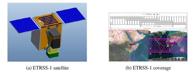
Figure 1. Simplest cost-reliability optimization model.
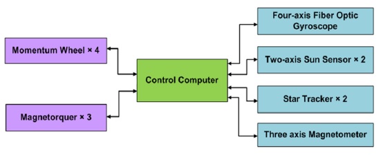
Figure 2. Si-on-Si Advanced VLSI Package Design.
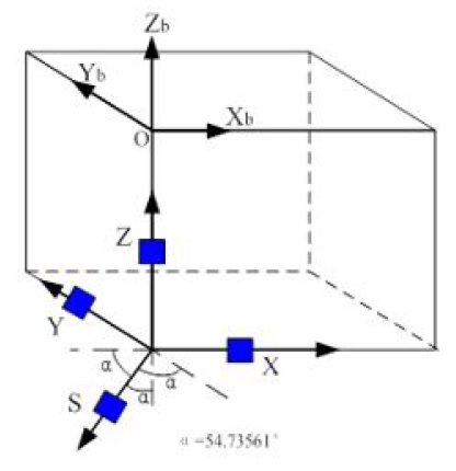
Figure 3. In an analytical thermal stress model the solder joints were approximated as short circular cylinders (left sketch), whose plane surfaces were subjected, at low temperature conditions, to radial tension; the highest stresses and strains acted, however, in the axial direction (right sketch).
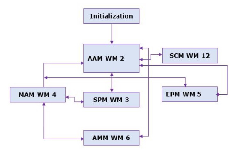
Figure 4. FOAT data (left): tests continued until half of the population failed; the wear-out portion of the experimental bathtub curve (right) is approximately of the same duration as its steady-state portion Experimental BTC for solder joint interconnections in a flip-chip Si-on-Si Bell Labs design . The arrow indicates the initial point of the IMP of the BTC, where the critical time derivative of the nonrandom SFR should be determined. It is the level of this derivative that helps to answer the basic "to BIT or not to BIT" question.
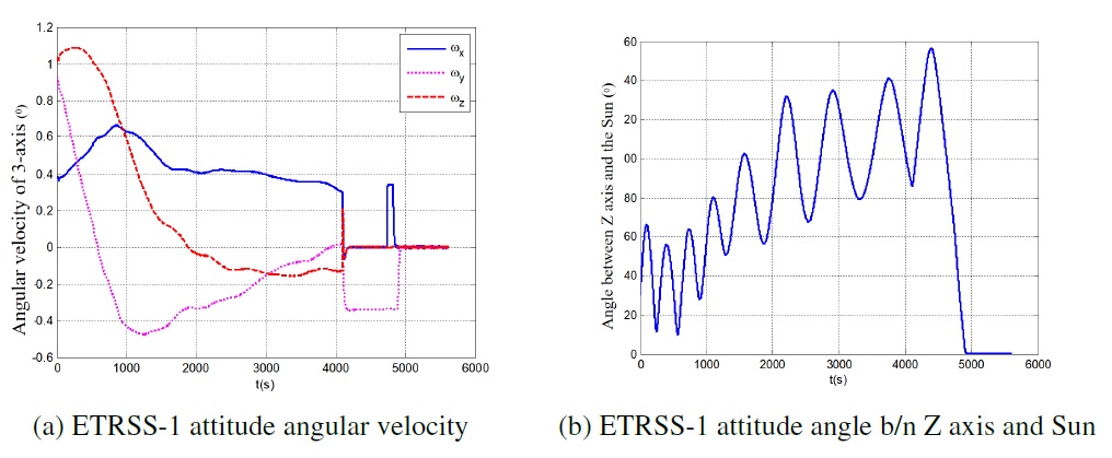
Figure 5. FOAT data (left): tests continued until half of the population failed; the wear-out portion of the experimental bathtub curve (right) is approximately of the same duration as its steady-state portion Experimental BTC for solder joint interconnections in a flip-chip Si-on-Si Bell Labs design . The arrow indicates the initial point of the IMP of the BTC, where the critical time derivative of the nonrandom SFR should be determined. It is the level of this derivative that helps to answer the basic "to BIT or not to BIT" question.
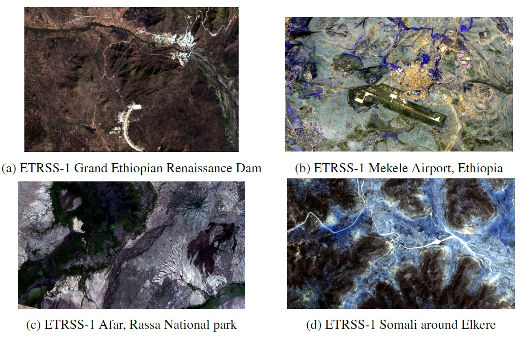

Figure 6. FOAT data (left): tests continued until half of the population failed; the wear-out portion of the experimental bathtub curve (right) is approximately of the same duration as its steady-state portion Experimental BTC for solder joint interconnections in a flip-chip Si-on-Si Bell Labs design . The arrow indicates the initial point of the IMP of the BTC, where the critical time derivative of the nonrandom SFR should be determined. It is the level of this derivative that helps to answer the basic "to BIT or not to BIT" question.
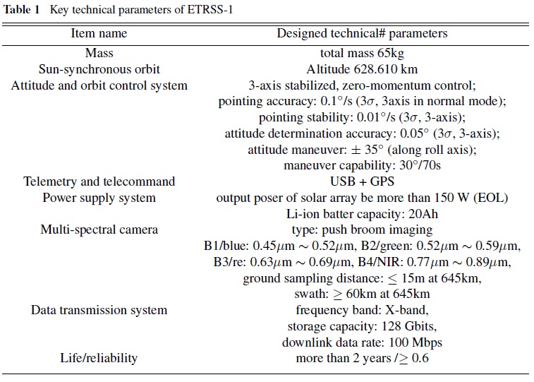

Table 1. Accelerated test types.
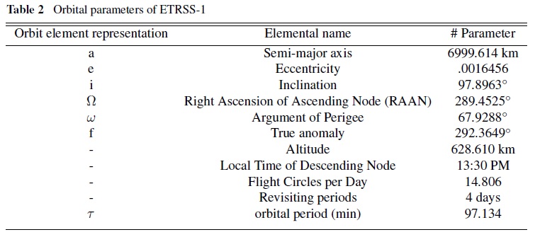
Table 2. Time-to-failure (TTF) in hours depending on the probability-of-non-failure and temperature.
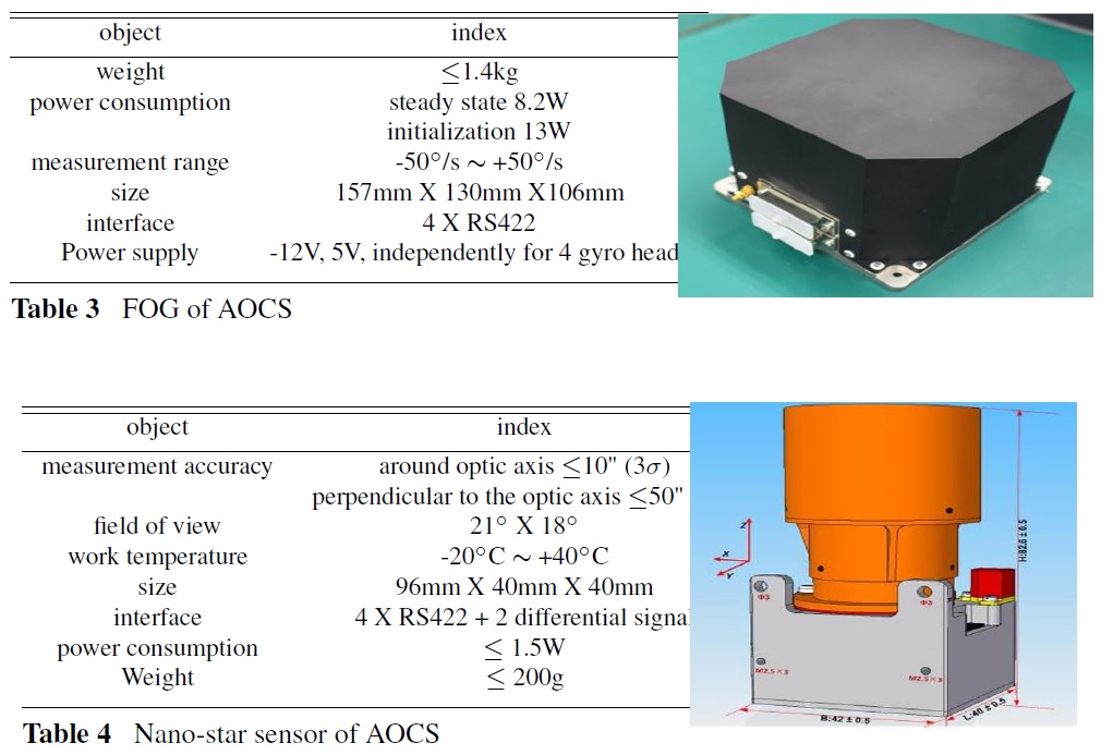
Table 3. The function ϕ (τ ) of the effective (“physical”) time and its (also “physical”) time derivative −ϕ′(τ ) . Table 4. The function ϕ (τ ) of the effective (“physical”) time and its (also “physical”) time derivative −ϕ′(τ ) .
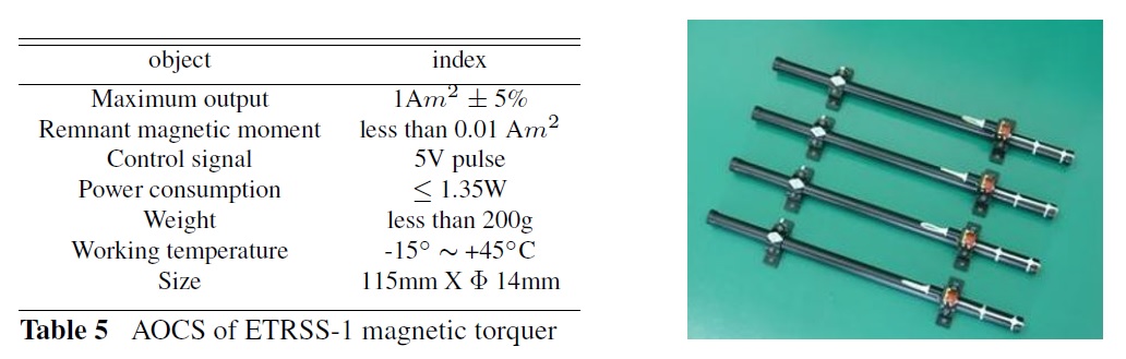
Table 5. Time-to-failure (TTF) in hours depending on the probability-of-non-failure and temperature.
Results and Discussion
AOCS’s Safe Control Mode of Operation
To complete the imaging mission, ETRSS-1’s AOCS collaborates
with other subsystems and will use several command sequences to
implement the cooperation by providing a satisfied attitude condition.
The AOCS on the ETRSS-1 satellite operates in six modes:
global attitude acquisition mode, sun pointing mode, maneuver
mode, earth pointing mode, attitude maintaining mode, and stop
control mode. Global attitude acquisition mode employs a fiber
optical gyroscope, a sun sensor, a magnetometer, a star sensor,
and actuators such as a momentum wheel to reduce the satellite’s
angular velocity to the required range, as well as magnetic torques
to stabilize the satellite after separation and drive the attitude close
to nominal. Sun pointing mode is the satellite’s normal operation
mode, and the attitude determination scheme is "FOG with
STS" or "FOG with the magnetometer," in which the attitude
is controlled by a momentum wheel, and the redundant angular
momentum is unloaded by magnetic torque. Maneuver mode is
an interim mode that uses the estimation of FOG to implement
attitude determination and momentum wheel to complete the attitude
maneuver. The satellite operates in a three-axis zero-attitude
earth-orientation mode, with attitude determination schemes
comprised of a fiber optical gyro coupled with a star sensor or a
fiber optical sensor coupled with a magnetometer. Attitude maintaining
mode is followed by maneuver mode to maintain the required
attitude, roll angle for imaging, or yaw 90° for calibration.
The satellite can enter the stop control mode autonomously or via
ground station control. In this mode, the central control unit no
longer works on attitude control and only performs measurement
and orbit calculation, and the output of the actuators is ZERO.
Figure 4 depicts the conditions for the ETRSS-1’s attitude control
and mode of operation, while Figure 5 depicts the attitude angle
and its corresponding angular velocity from January 2020 to 2023.
When the satellite is in Earth pointing mode and attitude maintaining
mode, its roll, pitch, and yaw angle vary between -0.1◦ and
+0.1◦. However, when in the earth pointing mode and attitude
maintaining mode, the corresponding attitude angular velocity of the satellite, including the roll and pitch angular velocity, varies
between -0.01◦/s and +0.01◦/s, while the yaw angular velocity
varies between -0.1◦/s and +0.1◦/s. Figure 6 shows the satellite’s
magnetic damping moment’s angular velocity during the initial
separation.
Optical multispectral image
Optical imaging has been one of the most on-orbit missions of
the ETRSS-1 microsatellite, due mainly to the satellite’s good attitude
performance. ETRSS-1 is equipped with a reinforced multispectral
camera module for optical imaging, with a Ground Sampling
Distance (GSD) of 13.4m at an orbit altitude of 628km and
a swath of 80km. Figure 6 depicts the optical imagery captured
by ETRSS-1 at various points in time and locations, including the
Grand Ethiopian Renaissance Dam construction image. The image
shows that the multispectral camera can capture the Earth,
proving that the AOCS for ETRSS-1 is suitable and effective.
Conclusion
The ETRSS-1 satellite has been in orbit for more than three years,
operating from a sun-synchronous orbit at an altitude of 628
kilometers, and has completed all missions successfully by providing imagery data via a ground control station facility located
at Entoto. The ETRSS-1 attitude and orbital control subsystem
is described in detail in this paper, and its on-orbit performance
is evaluated. According to the satellite’s original telemetry data,
the attitude angle of the satellite varies between -180◦ and +180◦
when in working modes other than Attitude Acquisition Mode
and Earth Pointing Mode.
Acknowledgment
The authors would like to thank the ETRSS-1 designer and operator
teams, as well as the engineers at China DFH satellite Co.Ltd,
for their support of the mission and commitment to making its
results public.
Declaration of Competing Interest
The authors declare that they have no known competing financial
interests or personal relationships that could appear to have influenced
the work described in this paper.
Funding Sources
This study received no specific funding from public, commercial, or non-profit funding agencies.
References
-
[1]. Luo X, Wang M, Dai G, Chen X. A novel technique to compute the revisit
time of satellites and its application in remote sensing satellite optimization
design.Int J AerospEng. 2017 Jan 31;2017(6):1-9.
[2]. Government of Canada. Remote Sensing Tutorials. 2015.
[3]. Ashley PR, Temmen MG, Sanghadasa M. Applications of SLDs in fiber optical gyroscopes. InTest and Measurement Applications of Optoelectronic Devices.SPIE. 2002 Apr 16;4648:104-115.
[4]. Liebe CC. Accuracy performance of star trackers-a tutorial. IEEE Trans Aerosp Electron Syst. 2002 Aug 7;38(2):587-99.
[5]. Wertz J, Everett D, Puschell J. Space mission engineering: the new SMAD, ser. Space technology library. Microcosm Press. 2011.
[6]. You Z, Sun J, Xing F, Zhang GF. A novel multi-aperture based sun sensor based on a fast multi-point MEANSHIFT (FMMS) algorithm. Sensors (Basel). 2011;11(3):2857-74. PubMed PMID: 22163770.
[7]. De Boom K. A novel digital sun sensor: Development and qualification for flight. In54th International Astronautical Congress of the International Astronautical Federation, the International Academy of Astronautics, and the International Institute of Space Law 2003 Sep (pp. AP-20).
[8]. Xie S, Lee GX, Low KS, Gunawan E. Wireless sensor network for satellite applications: a survey and case study. Unmanned Systems. 2014 Jul 4;2(03):261-77.
[9]. Díaz-Michelena M. Small magnetic sensors for space applications. Sensors (Basel). 2009;9(4):2271-88. PubMed PMID: 22574012.
[10]. Wang H, Chen L, Jin Z, Crassidis JL. Adaptive momentum distribution jitter control for microsatellite.J Guid Control Dyn. 2019 Mar;42(3):632-41.
[11]. Bhat SP, Dham AS. Controllability of spacecraft attitude under magnetic actuation.In42nd IEEE International Conference on Decision and Control (IEEE Cat.No. 03CH37475).IEEE.2003 Dec 9;3:2383-2388.
[12]. Starin SR, Eterno J. Attitude Determination and Control Systems. 2010. [13]. Ran D, Sheng T, Cao L, Chen X, Zhao Y. Attitude control system design and on-orbit performance analysis of nano-satellite—“Tian Tuo 1”. Chinese J Aeronaut. 2014 Jun 1;27(3):593-601.
[14]. Meng T, Wang H, Jin ZH, Han K. Attitude stabilization of a pico-satellite by momentum wheel and magnetic coils. J Zhejiang Univ-SCIENCE A. 2009 Nov;10(11):1617-23.
[15]. Garuma GF, Tessema SB, Tiky AY, Addis ZW, Adde YA, Giday NM, et al. First Ethiopian Remote Sensing Satellite (ETRSS-1): Mission information and overview. AuthoreaPreprints.2022 Nov 22.


