Computation Of Temperature Distribution On A Composite Aircraft Skin Protection Grid Due To Induced Electric Current During Flight under Thunderstorm Conditions
Theodore I. Lekas*
Department of Aerodynamics and Flight Mechanics, Hellenic Air Force Academy, Dekelia AFB, TGA 1010, Dekelia, Attika, Greece.
*Corresponding Author
Theodore I. Lekas,
Department of Aerodynamics and Flight Mechanics, Hellenic Air Force Academy, Dekelia AFB, TGA 1010, Dekelia, Attika, Greece.
Email: tlekas@hotmail.com
Received: April 18, 2022; Accepted: April 26, 2022; Published: April 28, 2022
Citation:Theodore I. Lekas. Computation Of Temperature Distribution On A Composite Aircraft Skin Protection Grid Due To Induced Electric Current During Flight under Thunderstorm Conditions. Int J Aeronautics Aerospace Res. 2022;09(01):270-273. doi: dx.doi.org/10.19070/2470-4415-2200035
Copyright: Theodore I. Lekas© 2022. This is an open-access article distributed under the terms of the Creative Commons Attribution License, which permits unrestricted use, distribution and reproduction in any medium, provided the original author and source are credited.
Abstract
The use of composite materials in aircraft manufacturing is more and more extended. Despite the considerable empty
weight penalty savings, this kind of material are vulnerable to lightning strikes due to their poor electrical and thermal
conductivity. This problem is solved by using full or partial metallic spray or a metallic grid imbedded into the composite
material. A lightning spark from a thundercloud to the ground can be considered as a wire traversed by an electric current
with a peak intensity of several hundred of Ampères. This way an ambient magnetic field is created which in turn, according
to Lenz law, creates an electric current circulating along the wires of the grid, producing heat. In this paper, a approach for
computing the temperature distribution inside a composite aircraft skin due to the presence of an ambient magnetic field
is presented. The goal is to compute the temperature rise inside the composite material so as to define areas of possible
long term damage.
2.Introduction
3.Literature Review
4.Dimensional analysis and Similitude
5.Design procedure of gating and runners
6.Experimental Procedures
7. Conclusion
8. References
Keywords
Magnetic Field; Stepped Leader; Electric Current; Composite Material; Aircraft Skin; Protection Grid; Thunderstorm.
List of Symbols
c = specific heat of the heated material (J/m/C); dT = temperature rise due to power dissipation (C); I
= electric current intensity (A); m = mass of the heating substance (kg); MAMB = Local ambient magnetic field strength (T)
MDIST= disturbance magnetic field strength caused by the aircraft (T); R = protection grid wire electric resistance (Ω); t =
time interval (s); μ = heating efficiency; ρ = resistivity of the material of the grid (Ωm).
Introduction
In recent years,composite materials saw a widespread use in aircraft
manufacturing for empty weight savings. The drawback of
these materials is their vulnerability in lightning strikes due to a
poor thermal and electric conductivity. To overcome this issue,
some solutions are adopted such as full or local aluminum coating
and aluminum or copper grid fully imbedded into the composite
material [1, 2].
In case of flight in a region where an ambient magnetic field is
present, such as in a thunder cloud region, according to Lenz law
[3] an electric current is created and circulates along the sides of
all meshes of the grid. This current produces heat everywhere on
the grid, which is transferred to the composite material.
Thunderclouds are usually present at altitudes up to 600 m to
900 m, so low altitude flight is concerned. A lightning spark from
such a cloud to the ground can be considered as a wire traversed
by an electric current with a peak of several hundred of Ampères
[4]. This way an ambient magnetic field is created. In this paper, a
method for computing the temperature distribution inside a composite
aircraft skin due to the presence of an ambient magnetic
field is presented. This method is based on Biot - Savart [3] and
Lenz laws. The temperature distribution corresponds to the highest
intensity peak in a lightning flash.
Presentation of the Approach
Aglobal frame is tied on the aircraft. The origin of this frame
lies on the nose of the aircraft, the x-axis is on the longitudinal
axis and directed towards the tail. The y-axis, parallel to the span, points to the right wing according to the pilot's view. The z-axis is
normal to the x - y plane and pointssuch that the global frame is
a right orthogonal one.
The thickness of the composite material is negligible as compared
to the aircraft dimension, like fuselage diameter or lifting surfaces
thickness. Since the grid is embedded into the composite material
it can be assumed that all grid points describe very accurately
the aircraft geometry. Based on this, the external surface of the
airplane is described by a number of points, the coordinates of
which are expressed in the global frame.In this study, the entire
aircraft is considered to be made from composite materials.
These points represent the grid points and are combined by three
or four to form panels, while each panel is consider as a plane one.
The number of points should be sufficient so as to accurately
describe the surface of the aircraft. Then, the coordinates of the
centroid G of each panel, the local (panel) frame G, t , l , n
→ → → , the
midpoint of each side GM common of two adjacent panels and
the length of each common side for all panels are calculated. The
unit vectors of the axes of the panel frame, namely n
→ (normal unit
vector pointing outwards),t
→ and l
→ (tangent vectors to the panel
surface) are such that the panel frame is also a right orthogonal
one.
Lenz law states that an induced electric currentis trying, by its
electromagnetic effect, to cancel the cause which creates it. This
means that along the sides of all meshesof the web, i.e. the sides
of each panel, an induced electric current will be induced, which
in turn will create a disturbance magnetic field so as to cancel the
ambient one. According to Lenz law, the ambient magnetic field
M →
AMB and the disturbance magnetic field M
→
DIST should satisfy everywhere
the following condition (equation 1):
EQ (1,2)
Figure 1 shows vectors DIST M
→
and AMB M
→
and the local panel
frame G, t , l , n
→ → → . All vectors in figure 1 are expressed in the global
frame.
As it is shown in figure 1, two mixed products can be formed.
Since a mixed product represents a volume, equation (2) is satisfied
only if the volumes represented by the mixed products are
equal (equation (3)).
EQ (3)
In equation (3) MDISTX, MDISTY, MDISTZ, MAMBX, MAMBY and MAMBZ
are the component of DIST M
→
and AMB M
→
in the global frame. MDISTX
, MDISTY, MDISTZ respectively are equal to (equations 4):
Ij
is the induced current intensity circulating along the sides of
panel j and mXIJ, mYiJ and mZiJ are the components of the magnetic
field induced at the centroid of panel I by a unit electric current
circulating in all sides of panel j . These component are calculated
according to the Biot - Savart law.
The Biot - Savart law states that a rectilinear electric conductor
traversed by an electric current I, induces at a point A a magnetic
field M
→
, (figure 2). The module of M
→
equals to (equation 5):
EQ (5)
In equation (5), μ0 = 4π10-7 Tm/A is the magnetic permittivity of
the air and d is the distance of point A from the conductor.Vector
B →
is normal to the plane formed by the rectilinear conductor
and point Aand points according to Maxwell rule, in this case as
shown in figure 2. It must be pointed out that the Biot - Savart
law is also used in potential flow aerodynamics where the roles of
I and B
→ are played by the vorticity Γ and the induced velocity V
→
respectively [5].
Equations (3) and (4) combined are giving the boundary condition
to be satisfied at any panel centroid (control point) Gi on the
aircraft skin.
By applying this boundary condition, to the centroid of N panel, a system of N x N linear algebraic equations is obtained. The
solutions of this system are the values and the sign of theelectric
current intensity Ij due to M
→
AMB and circulating on the sides
of allpanels approximating the external surface of the aircraft.
This computation is made using a modified in house aerodynamic
computer code, based on 3D vortex lattice method [5].
Once the value of I everywhere on the grid is computed, the corresponding
temperature rise, in Celsius degrees, can be calculated.
The expression of the temperature rise in a given material is expressed
by (equation 6, [9]).
where
R = electric resistance of the grid material (Ω), I = electric current
intensity (A), t = time interval (s), μ = heating efficiency, c
= specific heat of the heated material (J/m/C) and m = mass of
the heating substance (kg).
The electric resistance R is given by equation (7):
where
ρ = resistivity of the material of the grid (Ωm), L = length of the
conductor (m) and S = section area of the conductor (m2).
Results
A generic airliner geometry of 50 m fuselage length and 60 m
wing span is created. The linear algebraic equation system is
solved using a singular value decomposition method [6]. The aircraft
was in level flight and exposed to an ambient magnetic field
of various strength. This ambient magnetic field is considered as
parallel to the x-axis of the global frame.
As it was already said at the introduction, a lightning from a thundercloud
to the ground is approximated by a straight wire of
length equal to 900 m and traversed by an electric current of an
intensity peaking up to several thousand of Ampères, actually up
to 200000 A [8]. The intensity of the induced magnetic field at
various distances from the lightning and various flight altitudes up
to 900 m can be calculated according to Biot - Savart law. In table
1, the strength of the ambient magnetic field at various distances
(500 m, 1000 m and 1500 m) from the lightning and at 450 m of
altitude are presented.
These values are to be compared to the magnetic field of the
Earth which varies from 25.10-6T to 65.10-6 T [7] and obviously
in all cases MAMB is stronger.
In this study the grid is assumed to be made of aluminum so, c =
890 J/m/C and ρ = 2,65.10-8Ωm [10]. L is the length of the common
side of two adjacent panels of the grid. The density of the
aluminum equals to 2700 kg/m3. Since no data about the grid wire
diameter could be found, a typical fusel age skin thickness was
taken, in this case concerning a Boeing 787 with a skin thickness
of 0,99 mm. According to this, the grid wire diameter was taken
equal to 0,50 mm. In this case there is an electrical heating, soμ
=1. According to [8], the velocity to the ground of a step leader
is about 1,5.105 m/s. As it was already said in the introduction,
since thunderclouds altitude is up to 900 m, the duration of the
lightning flash is estimated at 0.006 s. Assuming that the induced
electric current will last as long as the lightning flash exists, t =
0.006 s.
Based on this, in figures 3, 4 and 5 the temperature rise distribution
in Celsius degrees inside the aircraft composite skin is shown
for distances of 500 m, 1000 m and 1500 m from the lightning
flash. In all figures, the color palette is modified in order to let the
highest values be also visible. For this reason in figure 3, the red
color corresponds to the value of 50 (maximum of the palette)
up to the value of 8312 degrees C (maximum of the result file). In
figure 4, the red color corresponds to the maximum of the palette
up to the value of 781 degrees C. Same in figure 5, where the red
color corresponds to the maximum of the palette up to the value
of 70 degrees C.
The closer to the stepped leader the highest the temperature rise,
as it was expected. On the other hand, in all cases, the wings seem
to be more affected than the fuselage and the tail unit. This is
due to the shape of the grid adopted here. It must be pointed out
that, in this study, the same points which describe the surface of
the aircraft define also the protective grid so that, the sides of the
panels on the surface of the aircraft are forming also the mesh
of the grid.
According to [11], the melting temperature of the carbon fiber
varies from 3652 to 3697 degrees Celsius. This means that at
some points the skin might be melted and cracks be formed. The
length of these cracks equals the length of the wire of the grid
beneath them. On the other hand, flight too close to a stepped
leader is not frequent. In order to clarify this problem, a structural
analysis should be made to investigate if these local damages have
an impact on flight safety in along term and how frequently they
must be monitored.
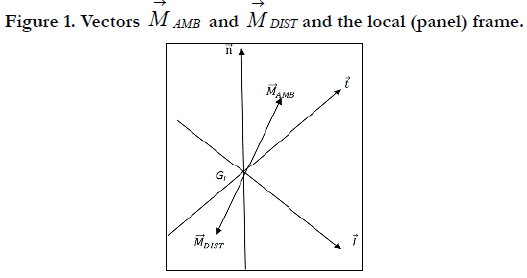
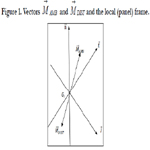
Figure 1. Vectors AMB M → and DIST M → and the local (panel) frame.
Figure 2: Magnetic field M → induced at point A by a conductor traversed by an electric current I.
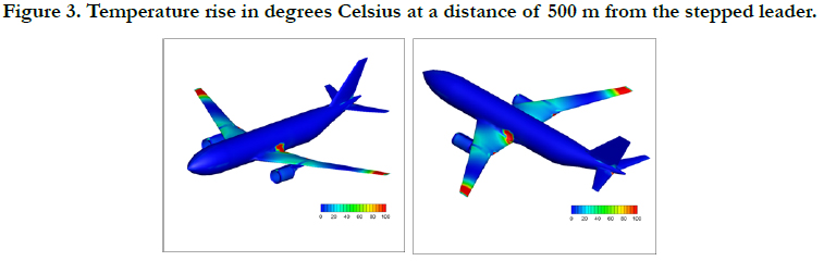
Figure 3. Temperature rise in degrees Celsius at a distance of 500 m from the stepped leader.
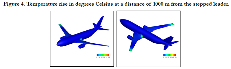
Figure 4. Temperature rise in degrees Celsius at a distance of 1000 m from the stepped leader.
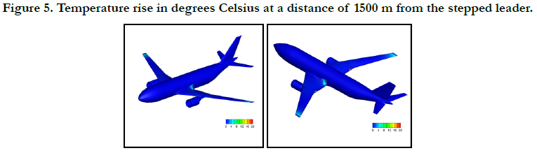
Figure 5. Temperature rise in degrees Celsius at a distance of 1500 m from the stepped leader.
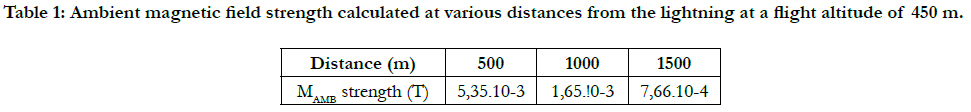

Table 1: Ambient magnetic field strength calculated at various distances from the lightning at a flight altitude of 450 m.
Conclusions
In this paper a numerical approach is presented, aiming to calculate the temperature rise distribution along all meshes of a metallic
grid embedded in the composite skin of an aircraft. This
knowledge permits to spotan immediate damage of the composite
skin due toa local high temperature rise, even of extremely
short duration. According to the results obtained, in some points
the temperature rise will locally make the composite structure to
melt. Of course, in this paper only the method is presented and
the same computation must be repeated based on the exact geometry
of the protecting grid of a real aircraft not on a generic one.
It must be established if a very local damage can compromise
in long term the stability of the entire structure, despite the low
frequency of occurrence of a flight too close to a stepped leader.
Acknowledgment
The author wish to thank the Parallel CFD and Optimization Unit
of the Department of Mechanical Engineering of the National
Technical University of Athens for its assistance in the post - processing
of the results.
References
- Wang F, Ma X, Zhang Y, Jia S. Lightning damage testing of aircraft composite- reinforced panels and its metal protection structures. Applied Sciences. 2018 Oct;8(10):1791.
- Alemour B, Badran O, Hassan MR. A review of using conductive composite materials in solving lightening strike and ice accumulation problems in aviation. JAerospTechnolManag. 2019 Mar 28;11.
- Grant IS, Phillips WR, Electromagnetism. 2nd ed. John Wiley & Sons, editor. Manchester Physics; 2008.122 p.
- Posey CA. The Living Earth Book of Wind & Weather. Readers Digest; 1994.
- Katz J, Plotkin A. Low - Speed Aerodynamics, From Wing Theory to Panel M Panel Method. Newyork: McGraw-Hill Inc; 1991.
- Press WH, Teukolsky SA, Vetterling WT, Flannery BP. Numerical Recipes in Fortran 77: The Art of Scientific Computing, Second Editon, Volume 1 of FORTRAN Numerical Recipes. Cambridge: University of Cambridge; 1997.
- Wikipedia, Earth's magnetic field, April 2022:
- Britannica, T. Editors of Encyclopaedia. 2020: 9.Cloud-to-ground lightning. Encyclopedia Britannica.
- Wikipedia, Electrical resistivity and conductivity, April 2022:
- Gardner G. Lightning strike protection for composite structures. High performance composites. 2006 Jul 1;14(4):44.
- https://www.americanelements.com/carbon-fiber-7440-44-0


