Design of a Solid Rocket Propulsion System
Adde Y. Alemayehu1*, Lulseged G. Solomon2
1 Director, Space Engineering Research & Development, and Project Manager of Satellite Manufacturing, AIT, Ethiopian Space Science & Technology Institute, Addis Ababa, Ethiopia.
2 Associate Researcher II, Space Engineering Research & Development Directorate, Ethiopian Space Science & Technology Institute, Addis Ababa,
Ethiopia.
*Corresponding Author
Adde Y. Alemayehu,
Director, Space Engineering Research & Development, and Project Manager of Satellite Manufacturing,
AIT, Ethiopian Space Science & Technology Institute, Addis Ababa, Ethiopia.
Tel: 0911894843
Email: kibret10@gmail.com
Received: May 30, 2020; Accepted: July 06, 2020; Published: July 17, 2020
Citation:Adde Y. Alemayehu, Lulseged G. Solomon. Design of a Solid Rocket Propulsion System. Int J Aeronautics Aerospace Res. 2020;7(2):224-229. doi: dx.doi.org/10.19070/2470-4415-2000027
Copyright: Adde Y. Alemayehu© 2020. This is an open-access article distributed under the terms of the Creative Commons Attribution License, which permits unrestricted use, distribution and reproduction in any medium, provided the original author and source are credited.
Abstract
Rocket Propulsion is a class of jet propulsion that produces thrust by ejecting stored matter called propellant. A solid-propellant
rocket is a rocket with a rocket engine that uses solid propellants (fuel/oxidizer). A simple solid rocket motor consists
of a chamber/casing, nozzle, grain (propellant charge), and igniter. The earliest rockets were solid-fuel rockets powered by
gunpowder; they were used in warfare by the Chinese, Indians, Mongols and Persians, as early as the 13th century. The latest
rockets use Aluminum perchlorate, as oxidizer, Aluminum as a fuel and HTPB as a fuel binder and Isoforondisocyanat as
a curative catalyst. Design of solid rocket propulsion system begins with the total impulse required, which determines the
fuel/oxidizer mass. Grain geometry and chemistry are then chosen to satisfy the required motor characteristics. This paper
presents design of solid rocket propulsion system for a sounding rocket. Different materials were selected for different parts
of the propulsion system based on the factors like density, cost and availability. The design result shows that the mass of
propellant is 960 kg with volume of 0.546176383 m3 in the length of 1.944787875 m.
2.Introduction
3.Solid Propellant Compositions
4.Conclusion
5.Acknowledgements
6.References
Nomenclature
AT = nozzle throat area
AB = Burning surface area
Pt = motor chamber pressure
Kn = Ratio of Burning surface area to the nozzle throat cross-section area
a = Burn rate pressure coefficient
α = Burn rate pressure conversion factor, MPa to Pa units (α =1 000 000n)
ρ = propellant mass density
c* = propellant characteristic exhaust velocity
n = Burn rate pressure exponent
m = mass of propellant
V = volume of propellant
Ac = area of circle
Atr = area of triangle
Ag = segment area
At = total front area of propellant
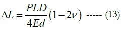
ΔL = expansion longitudinally in inches,
ΔD = expansion diametrically,
L = length of the case in inches,
D = Inner diameter of the case in inches,
E = Young’s Modulus of Elasticity measured in kilo pound/in2 (or 1000 lb/in2),
D = Casing thickness in inches,
V = Poisson’s ratio
HTPB- Hydroxyl Terminated PolybutadieneAT = nozzle throat area
Introduction
PROPULSION a broad sense is the act of changing the motion
of a body. Propulsion mechanisms provides a force that moves
bodies that are initially at rest, changes a velocity or overcomes
retarding forces when a body is propelled through a medium
[1]. Rocket propulsion is a class of jet Propulsion that products
thrust by ejecting stored matter called propellant. Rocket propulsion
system can be classification according to the types of energy
source, according to basic function, and according to types
of function. According to the energy source rocket propulsion
can be classified as chemical, nuclear, and solar. According to the
basic function we can classify it as booster staging, sustainer, attitude
control, orbit station keeping, etc. According to types of
function rocket propulsion can be classified as aircraft, missile,
assisted take-off, space vehicle, etc. A solid propellant rocket, a
kind of chemical rocket propulsion, is a simple propulsion system
that consists of a high-pressure vessel that contains all the solid
components needed. The fuel and oxidizer are intimately mixed
together and cast into a solid mass, called grain. The propellant
grain usually has a hole down the center of the chamber, which is
called perforation, and may be shaped in various ways.
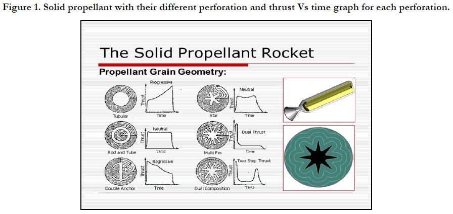
Figure 1. Solid propellant with their different perforation and thrust Vs time graph for each perforation.
The functioning starts with an ignition system whose firing causes the beginning of a chemical reaction over the solid surface in the perforation. Once ignited, a simple solid rocket motor cannot be shut off, as it contains all the propellants needed for combustion all together in the chamber where they are burned. After the ignition, the propellant grain burns on the entire inner surface of the perforation, until the end of the propellant. The heated gases generated during the solid combustion pressurize the inside of the chamber and are finally expelled through a nozzle which accelerates them producing the reaction force needed to move, known as thrust [2].
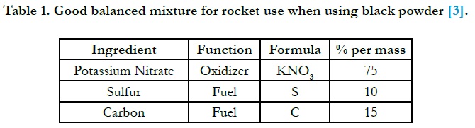

Table 1. Good balanced mixture for rocket use when using black powder [3].
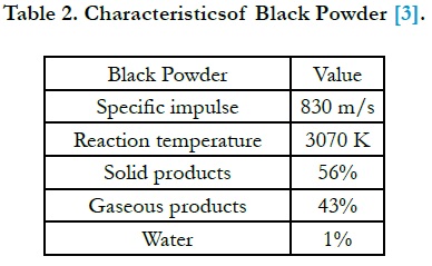
Table 2. Characteristicsof Black Powder [3].
By the wording ‘solid’, it may imply to us that the propellant composition
is in some sort of hardened state. In the old days (but
still around today) black powder, a mechanical mix consisting of
potassium nitrate (KNO3), sulfur (S) and charcoal (C) would either
be compressed mechanically or by adding rubber Arabicum
(natural rubber) to solidify the otherwise powdery state of the
ingredients. Both methods were essential for a good functioning
of a rocket in order to ensure smooth combustion with time
whereas a propellant in just powdered state would more likely lead
to unpredictable burning with the increased risk of motor rupture
(explosion) [3]. When black powder burns, it does this with a high
temperature flame producing huge amount of smoke and solid
products.
Black powder is still in use as a rocket propellant, but only found
in fireworks and model rocket motors. Black powder may occasionally
be used for igniting solid propellant rocket motors. Due
to its low specific impulse, hygroscopic and powdery nature, the
propellant has for long been replace by far more energetic, mechanical
strong and stable compounds.
Modern solid propellants consist of ingredients that are in a solid
and liquid state during the mixing process. All solids are typically
based on an oxygen rich salt like ammonium perchlorate (NH4ClO
4) as the oxidizer and aluminum powder (Al) as fuel. Ammonium
perchlorate contains 54.5% per weight oxygen. The liquid
part is often an industrial long chain polymer. The purpose of the
polymer is to harden and thereby fixate the powered based part
of the mix.
A commonly used polymer is Hydroxyl-Terminated Polybutadiene
or HTPB (CxHyOz). The hardening process is triggered by
adding a hardener agent like Isoforondiisocyanat (C12H18N2O2) in
order to start the cross-polymerization process. After mixing the
propellant typically has a viscous state. The mixture is then poured
by gravity or by pressure over to the rocket chamber where a casting
mandrel is placed in the center of the engine. The geometry
of the mandrel will vary from program to program. Often it can
have a star shape. When the propellant has filled the allowable
volume, the motor will be transported to a curing oven.
Typically, the mix will be allowed cure for a weekly long period at
an elevated temperature (60-70°C). When cured, the propellant
grain can be compared to the sensation of touching an ink rubber.
A modern composite propellant charge can contain eighteen
different ingredients. The main important ones are the molecule
holding the oxygen (oxygen rich salt) and a fuel, e.g. aluminum,
beryllium or the fuel binder itself. Other minor per mass ingredients
are additives for chemical stability, pot life plasticizer, burn
rate catalysts, anti-softening, curing additives, and more [3].
A modern composite propellant can give 2500 m/s (255 s) specific
impulse.
Let take thrust 60 kN= 60,000 N.
mass of propellant consumed per second = thrust/ Specific impulse
(Isp) ----- (1)
mass of propellant consumed per second =60,000 (N) /2500(m/s)
= 24 (kg/sec)
Mass of expelled propellant =mass of propellant consumed per
secondEffective firing duration ----- (2)
Effective firing duration = 100,000 (m) / 2500 (m/s) = 40 sec
Mass of expelled propellant = 24 (kg/sec) * 40sec = 960 kg.
Total impulse = thrust * effective firing duration -----(3)
Total impulse=60,000 N * 40 sec =2,400,000 N-sec
Composite propellants are used in everything from small tactical
rocket motors for missiles to the big and very powerful solid
rocket boosters for launch vehicles. To balance the amount of
oxygen with the amount of fuel is important in rocketry. In chemistry
we know that a stoichiometric reaction is a complete chemical
reaction between the amounts of reactants (oxidizer + fuel)
and products. This is not always practically possible or wanted
based on performance. As an example: in solid propellant mixtures
you may find that theoretically you should have above 88%
oxidizer concentration in your mix, since this will give you higher
performance (specific impulse). That can sometimes be difficult
to achieve since you may have other requirements on your propellant
like mechanical strength and chemical bonding properties.
Table 3. Typical modern composite solid propellant mixture [3].
Table 4. Modern composite solid propellant mixture with corresponding mass.
In modern solid propellant mixes we have to assess the balance of three major parts, the amount of oxidizer, the amount of fuel and the amount of binder. All solid propellants are potentially dangerous mixtures. This is so since they contain oxidizer and fuel already mixed together. The composition may be fairly robust but still it may just need a spark to start the combustion. As soon as the composition has started to burn, it will be very difficult or impractical to stop it.
Depending on the chemical composition used, a solid propellant can burn slowly or not at all in at ambient pressure. However, if you ignite the same propellant in a confined volume, you may observe an opposite result, a quick reaction. Most solid propellants burn at a higher rate at a higher pressure. Sometimes a rocket engineer wants to increase the propellant burn rate withoutincreasing the pressure so much. For such cases we often add in iron oxides (e.g. Fe2O3) in amounts of 0.5 – 3.0% all depending on the chemicals used and the needs required. For such cases iron oxides behaves as a burn rate catalyst [3].
Kn is the ratio of the burn area of the propellant to the area of
the nozzle throat. Add up all the exposed (uninhibited) surfaces
of the propellant to get the burn area (the inside core area, plus
the top & bottom faces of all the grains, for example). Call this
area AB for burn area. Then, find the area of the nozzle's throat:
AT = ¼ pi * DT
2 where DT is the throat diameter. If it has multiple
throat openings, add up all the throat areas.
Kn = AB/AT ----- (4)
Keep in mind that Kn is an instantaneous, time-varying value it is
continually changing as the propellant burns. Depending on the
grain geometry, the Kn may increase or decrease (or both) during
the total burn time of the motor. The intial Kn is important because it affects how easily the motor will ignite. The maximum
Kn or peak Kn is important because it is directly related to the peak
chamber pressure. During the start-up phase of the motor burn,
just after ignition, a sufficient initial Kn provides a transition to
the equilibrium phase of combustion. If the initial Kn is too low,
the motor may not reach steady-state burning. As the motor begins
to come up to pressure, the combustion gases begin to flow.
When there is gas flow there is reduced pressure.
Table 5. Three common proportion modern propellant with corresponding specification [9].
If the pressure drop is high enough, the motor will cease (stop) to ignite (a “chuff ”). If there is sufficient residual heat and pressure, the motor will ignite again and continue chuffing until the Kn increases enough to transition to steady combustion. As a practical guideline, an initial Kn of 220 is sufficient to produce reliable ignition. If the propellant is more energetic (finer AP or catalyzed), a lower initial Kn (180 to 200) could be enough. If the propellant has low-energy additives (fuel rich or low-energy effects chemicals), a higher Kn (240 or higher) may be required [4].
Table 6. Aluminized Ammonium perchlorate as a function of chamber pressure for expansion to sea level [9].
The term steady-state infers the operating condition whereby chamber pressure is solely a function of grain burning-surface area. In other words, the generation of combustion gases, and outflow of gases through the nozzle, are in a state of equilibrium (balance). Therefore, this excludes the initial pressure build-up as well as the pressure tail-off at burnout [5].
initial Kn =195.7 and let take nozzle throat area AT = 0.00397503904 m2
AB = 0.77791514 m2.
A pressure vessel is a container designed to hold gases or liquids
at a pressure substantially different from the ambient pressure.
Design involves parameters such as maximum safe operating
pressure and temperature, safety factor, corrosion allowance and
minimum design temperature (for brittle fracture). Many pressure
vessels are made of steel, Some are made of composite materials,
such as filament wound composite using carbon fiber held
in place with a polymer due to the very high tensile strength of
carbon fiber these vessels can be very light, but are much more
difficult to manufacture [6]. Choosing the grain geometry is the
primary way to control the overall Kn curve for a motor design.
The way the surface area of the propellant changes as the burn
progresses is how the Kn curve will be shaped. Also, the nozzle
throat diameter will scale the overall Kn curve inversely proportional
to the square of the throat diameter [4].
AB = C * L ----- (6)
C = 0.4 m
L = 1.944787875 m
ρ = m/v ---- (7)
V = 0.546176383 m3
A = V/L ----- (8)
At = 0.280841108 m2
Atr =(1/2) at * bt sin ct ----- (9)
Atr = 0.002490529833 m2
Ag=θ/( 360) πr2-(1/2) ab sin c ------ (10)
Ag = 0.003380903844 m2
Ac = At - (Atr + Ag) -----(11)
Ac = 0.274969675 m2
Ac = π (r22 - r21) ----- (12)
r2 = 0.302976831 m
Different materials were selected for different parts of the motor. Major factors like density, cost and availability affected the selection process [7].
It is an alloy of aluminum with magnesium and silicone as major alloying elements and is widely used in aircraft construction
industry. With a density of 2.7 g/cm3 it is best suited for experimental
projects in aerospace and its ease of machining is advantageous.
This type of aluminum is incredibly strong, relativelylightweight
and is commonly used as motor casings for commercially
produced amateur rocket motors. A minimum diameter rocket is
a type of rocket which uses the walls of the rocket airframe as
the casing for the motor, whereas traditional collegiate and amateur
building methods use a motor mount to fit a motor which
has a smaller diameter than the airframe. High-altitude rockets
are incredibly efficient when they are built minimum diameter,
therefore maximizing the potential amount of solid propellant.
Figure 2. Propellant perforation and segment area portion with dimension.
Figure 3. Symmetrical view of total propellant.
The following properties of the alloy were observed for calculation of design pressure and burst pressure of the casing.
Two equations can be used to approximate the expansion of a motor casing, for both length and diameter, during a propellant burn due to chamber pressure. For 6061-T6 Aluminum, the elongation at break is 12%, the Young’s Modulus is 10,000 ksi, Poisson’s Ratio is 0.33 [8].
Figure 4. Front, top and side view of propellant.
Table 7. Properties of Al 6061-T6 [8].
d = 0.04147165987 mm
Full-scale nozzle surface temperature history can be approximated in a small-scale nozzle by appropriate selection of wall thickness [9] take factor of safety 120 and d = 5 mm.
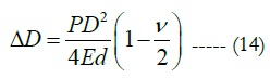
ΔD = 0.001488150906 mm
Conclusion
Design of solid rocket propulsion system includes determination
of the total impulse required, the weight of fuel/oxidizer, grain
geometry, and grain chemistry that satisfy the required motor
characteristics. The paper presented selection of modern composite
solid propellant mixture with a mass 960kg, volume of
0.546176383 m3 and 1.944787875 m in length. The main chamber
area portion is divided in to three segments: Segment area =
0.003380903844 m2, triangle area = 0.002490529833 m2 and area
of circle=0.274969675 m2. The values of burning area and initial
area ratio (Kn) are 0.77791514 m2 and 195.7 m2 respectively.
Acknowledgements
They author of this paper appreciate Ethiopian Space Science and
Technology Institute, Space Engineering Research and Development
Directorate staff members for their valuable support and
contribution.
References
- [1]. http://catdir.loc.gov/catdir/samples/wiley031/00027334.pdf on 25 May 2020.
- Navarrete-Martin L, Krus P. Sounding Rockets: analysis, simulation and optimization of a solid propellant motor using Hopsan. Transportation Research Procedia. 2018 Jan 1;29:255-67.
- https://www.narom.no/undervisningsressurser/sarepta/rocket-theory/rocket- propellants-2/solid-propellants/ on 25 May 2020.
- John SD.THE PROPELLANT: NOZZLE AREA RATIO, A Practical Guide to Kn. 2007.
- Richard Nakka’s, Experimental rocket web site. https://www.nakka-rocketry. net/design1.html
- https://en.wikipedia.org/wiki/Pressure_vessel
- SiddhantS.Solid Rocket Motor for Experimental Sounding Rockets. Advances in Aerospace Science and Applications. 2013; 3(3): 199-208.
- Jackson S.Design of Nozzle for High-Powered Solid Rocket Propellant. Undergraduate Journal of Mathematical. 2018; 9.
- Freche JC, Johnston JR, Signorelli RA. Performance of rocket nozzle materials with several solid propellants. NASA TECHNICAL NOTE. 1966.


