Axial Stiffness Variation of Thin Walled Laminated Composite Beams Using Piezoelectric Patches- a New Experimental Insight
H. Abramovich
Faculty of Aerospace Engineering, Technion, I.I.T., Haifa, Israel.
*Corresponding Author
H. Abramovich
Faculty of Aerospace Engineering, Technion, I.I.T.,
Haifa, Israel.
E-mail: haim@technion.ac.il
abramovich.haim@gmail.com
Received: April 07, 2016; Accepted: May 26, 2016; Published: May 27, 2016
Citation: H. Abramovich (2016) Axial Stiffness Variation of Thin Walled Laminated Composite Beams Using Piezoelectric Patches- a New Experimental Insight. Int J Aeronautics Aerospace Res. 3(2), 97-105.DOI : dx.doi.org/10.19070/2470-4415-1600012
Copyright: H. Abramovich© 2016. This is an open-access article distributed under the terms of the Creative Commons Attribution License, which permits unrestricted use,distribution and reproduction in any medium, provided the original author and source are credited.
Abstract
Altering the natural frequencies of slender thin walled laminated composite beams by changing its stiffness has been reported in the literature. This had been performed either using optimal mechanical and thermal induced stresses or using collocated piezoelectric patches bonded on the structure. It was shown that for the cases of a beam equipped with piezoelectric patches, restraining the beam’s axial displacements at its two ends can lead to either softening or stiffening of the beam stiffness, as a function of the voltage supplied to the patches.
However, when those structures behave like a cantilevered beam, or a free-free beam, classical beam theories show that the lateral vibrations of those beams cannot be altered by applying a constant electric voltage to the collocated surface bonded piezoelectric layers or patches. This occurs because the resultant force on each cross section of the beam is always identically zero (due to the fact that no axial external forces are applied on the beam).
It is the aim of the present manuscript to show that under certain circumstances one can alter also the natural frequencies of a cantilevered piezo laminated beam. The present paper will investigate this phenomenon, and provide a new insight into this topic.
2.The Model
2.1.The theoretical model
2.2.The experimental model
2.3.The finite element model
3.Results
4.Discussion and Conclusions
5.Acknowledgments
6.References
Introduction
The issue of utilizing piezoelectric patches to control and/or improve the natural frequencies and/or buckling behavior of thin walled structures, like beams and plates, had been investigated and discussed in the literature.
Waissman & Abramovich [1, 2] published results on stiffening effects of beams, by calculating the vibrations of beams with piezoelectric layers or patches bonded on their surfaces. Their theoretical model was based on Timoshenko's beam theory (first order shear deformation theory), which takes into account shear deformation and rotational inertia effects while in-plane deformations of the cross sections, namely geometric variations of the cross sections, can be neglected.
The investigation of the stiffening phenomenon had been performed in two steps:
a) Initially a constant voltage was applied to the electrodes of the piezoelectric layers or patches. Since the axial displacement at the two ends of the beam was constrained, axial resultant cross sectional forces were developed along it. In the case of asymmetric cross sections bending may also occur, but the present investigation and discussions, for the sake of simplicity, is confined to symmetric cross sections only. One should note that only the in-plane (axial) boundary conditions are effective, while the lateral boundary conditions have no influence on the phenomenon at this first step.
b) At the second step, small lateral vibrations were superimposed on the initially compressed or tensed beam (depending if the applied voltage was positive or negative). At this moment the effect of the previous step was introduced solely through the cross sectional resultant axial force that acted along the beam. During the second stage of the investigation, the lateral boundary conditions defined the frequencies and mode shapes of the vibrations, which were not influenced by the axial constraints. Similar results showing the change in the stiffness of a structure with piezoelectric patches had been shown by other studies in the open literature (see for example Refs. [3-13]).
The above presented research [1, 2], that supported previous similar results that had been obtained by other researchers [3-8], aroused some interest and lead to various discussions on the nature of the phenomenon. According to the above model, the entire phenomenon depends on the resultant axial force that acts along the beam, which is a result of the axial constraints at the beam's boundaries. In the case of a cantilevered type beam (namely, clamped/free boundary conditions) the cross sectional resultant axial force is always equal to zero. Thus, it was concluded by various readers of [1, 2] that, it is definitely impossible to affect the lateral vibrations of a cantilevered beam by applying a constant voltage to piezoelectric layers or patches that are bonded on its upper and lower surfaces.
The purpose of the present study is to show a simple example, accompanied by experiments, of a cantilevered beam where the lateral vibrations are affected significantly by applying a constant voltage to piezoelectric patches that are bonded on its surfaces and to further explain the study which has been already communicated in a short note [16]. The effect in this case is due to small variations of the geometry of the beam's cross sections, due to the small lateral vibrations. These small variations of the cross sectional geometry result in bending moments, about the cross sectional center, due to the internal stresses that are created during the above described step one. This bending moment affects the lateral vibrations even though the resultant cross sectional axial force is equal to zero.
The following study shortly presents the theoretical model of a beam with continuous piezoelectric layers, already available in the literature [1, 2], followed by the experimental model of the work. To be able to evaluate the experimental results, a finite element model was constructed using the ANSYS code [18], enabling the calculations of a beam with discrete piezoelectric patches.
The Model
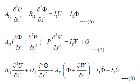
The employed theoretical model, based on FSDT (first order shear deformation theory), which is also known as Timoshenko’s beam theory [1, 2] is presented in Figure 1. It consists of a laminated composite beam under lateral and axial loads. The beam includes continuous piezoelectric layers, beside composite structural ones. The assumed displacements are: the lateral displacement, W (x,t), the axial displacement U (x,t) and the rotation of the cross section of the beam (around y axis), Φ (x, t). The equations of motion for this model can be written as (see also Refs. [14,15]):
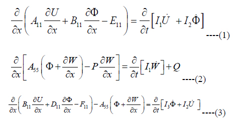
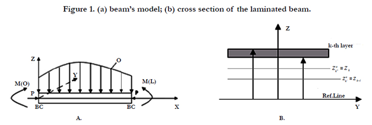
Figure 1. (a) beam’s model; (b) cross section of the laminated beam.
with their associated possible boundary conditions:
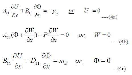
where pm and mm, the generalized axial load and moment, inluding the influence of the piezoelectric layers, are 1†:

For uniform properties along the beam, the equations of motion become:
where A11, B11, D11, A55 are the usual stiffness coefficients of a com posite beam (including the piezoelectric layers), I1,I2,I3 are the mass moments of inertia and E11 and F11 are defined as :
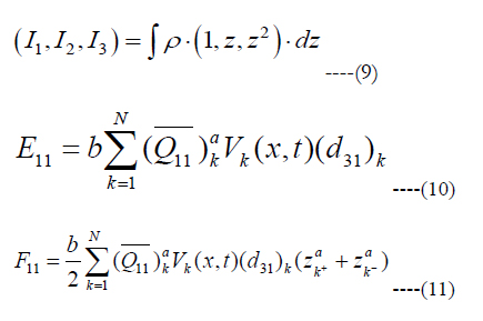
ϱ is the density of each layer of the beam, Vk(x, t) is the voltage applied to the k-th piezoelectric patch, (d31)k is the piezoelectric coefficient of the k-th patch and (¯Q11)ak is the stiffness of the k-th actuator.
Assuming

where ω is the natural frequency of the beam’s vibration and substituting in Eqs. (6-8) one obtains:
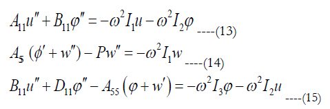
where ( )' and ( )" represent first and second differentiation with respect to x, respectively.
Decoupling the equations (see [14, 15]) for the general case,yields the following expressions for the assumed displacements and angle:
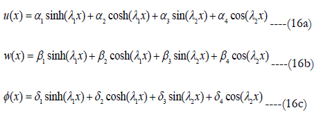
Application of the appropriate boundary conditions would enable to calculate the natural frequencies of the beam in the presence of induced axial compression. For the case of discrete piezoelectric patches, and correctly modeling of the problem, use of a finite element code is advised.
The experimental model was mainly made of glass-epoxy, having a uniform rectangular hollow cross section. Two glass-epoxy plates were glued at the root and tip cross sections (see Figures 2 and 3). The centers of these plates, namely the centers of the root and tip cross sections, were connected by a 0.6 mm steel wire. Three pairs and later on six pairs of piezoelectric patches were bonded on the upper and lower surfaces of the beam. To be able to apply relatively high voltages (from -500 up to 1500 V), the piezoelectric patches were MFC (Macro Fiber Composite type M-2814-P1) ones, manufactured by Smart Material Corporation [17]. The MFC was originally developed at NASA’s Langley Research Center for aerospace applications, and is an innovative actuator that offers high performance and increased flexibility. It consists of rectangular piezo-ceramic rods, sandwiched between layers of adhesive and electrode polyimide film. The piezoelectric patches were electrically connected in parallel, thus identical voltage was applied to all of them.
To monitor the behavior of the beam, pairs of strain gages were bonded along the upper and lower surfaces of the beam and at the beam’s root (see Figures 2 and 3).
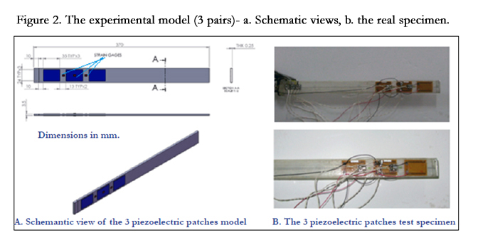
Figure 2. The experimental model (3 pairs)- a. Schematic views, b. the real specimen.

Figure 3. The experimental model (6 patches) - a. Schematic views, b. the real specimen.
The ANSYS finite element code [18] was employed to calculate both the static and dynamic response of the beam with both 6 (3 pairs) and 12 (6 pairs) piezoelectric patches bonded on its surfaces. Within this code, a dedicated element enables the user to add to the normal degrees of freedom, the geometric displacements, an another degree of freedom, the voltage (applied or generated) at the nodes of the element. The beam was modeled using 4480 shell type elements; the steel wire was modeled using 112 beam elements, while the piezoelectric patches were modeled using 1160 elements which were described earlier. To increase the accuracy of the model, it was found that the masses of the patches should be included in the calculations.
Results
The applied voltage was increased in steps of 50 [V]. At each voltage level the strains along the beam were recorded. Then the beam was excited using a shaker and the response was measured using Lissajous figures, yielding the first natural frequency of the beam.
First the three pairs piezoelectric experimental model was tested (Figure 2). As can be seen from Figure 2, the three strain gages pairs were bonded on both sides of the beam, before the second patch (S.G. 1 & 4), on the second patch (S.G. 2 & 5) and right after it (S.G. 3 & 6). The strain gages readings are given in Figure 4. for the static case.
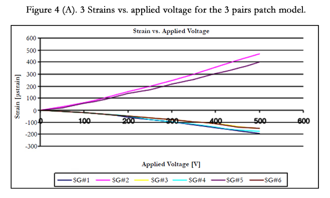
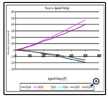
Figure 4 (A). 3 Strains vs. applied voltage for the 3 pairs patche model.
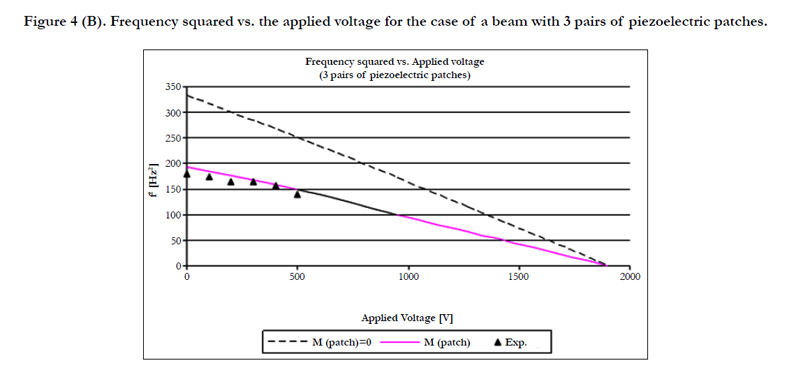
Figure 4 (B). Frequency squared vs. the applied voltage for the case of a beam with 3 pairs of piezoelectric patches.
Note that strain gages number 2 &5 are located on the piezoelectric patches and are in tension, while strain gages number 1,4,3,6 are on the beam and therefore in compression. Figure 5 presents the results of the investigation of whether to include the masses of the patches in the calculation of the natural frequencies or not. It is clear that masses of the piezoelectric patches play an important role in the dynamic behavior of the beam and therefore should be included in the finite element calculations. This was done throughout the testing campaign.
Another finite element investigation was performed to find the minimal number of piezoelectric patches capable of inducing buckling in the tested beam in the vicinity of 1000 [V], the maximal voltage that can be applied to the piezoelectric patches using the laboratory amplifier. Figure 5a presents the results for 6 and 7 pairs of piezoelectric patches bonded on the tested beam. Due to shortage in patches it was decided that the 6 pairs model would be the final testing model.
Figure 5b, presents a comparison between tests and FE calculations up to an applied voltage of 500 [V]. The accompanying static readings of the strains located at the beam’s root are shown in Figure 6.
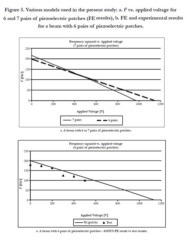
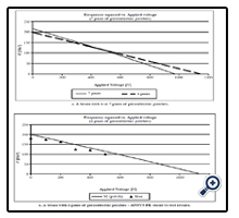
Figure 5. Various models used in the present study: a. f2 vs. applied voltage for 6 and 7 pairs of piezoelectric patches (FE results), b. FE and experimental results for a beam with 6 pairs of piezoelectric patches.
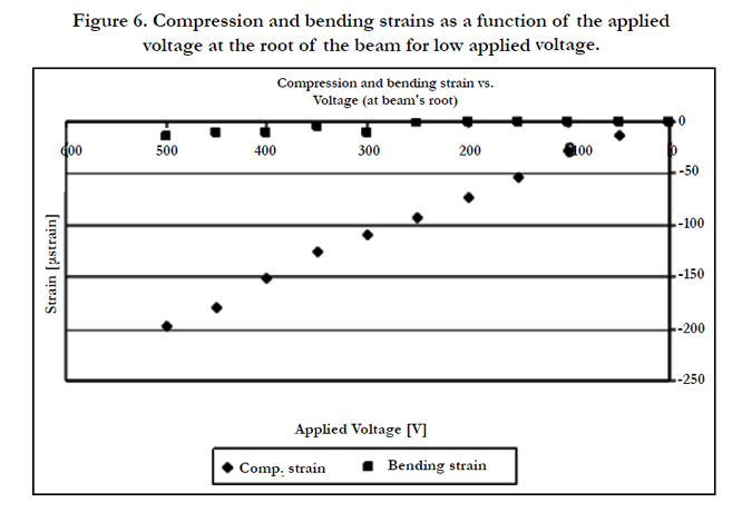
Figure 6. Compression and bending strains as a function of the applied voltage at the root of the beam for low applied voltage.
Figure 7 presents a comparison between the frequencies that were measured during the test and the finite element calculated values. In general, there is a good agreement between both results. Initially the experimental results are lower than the calculated ones. The reasons may be incomplete clamping and added mass associated with the cables connecting the patches to the voltage source and the strain gages to the strain recorder. At higher voltages the experimental results exhibit a better agreement with the calculations. The square of the frequency is reduced almost linearly with the increase in voltage. The point where the natural frequency becomes zero indicates buckling of the beam. It is well known that because of the initial curvature that always exist in test models (initial imperfections) large bending deformations occur before buckling is reached. The measurement of the natural frequencies stopped at 850 [V], as no natural frequencies could be detected above it.
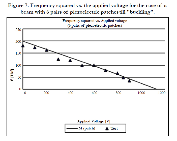
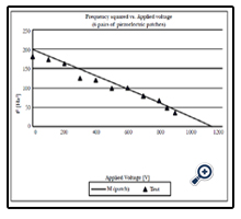
Figure 7. Frequency squared vs. the applied voltage for the case of a beam with 6 pairs of piezoelectric patches till "buckling".
A common method of determining the experimental buckling load (or buckling voltage in the present case) is to use a South well plot, as shown in Figure 8. In this figure the bending strain at the root of the cantilevered beam is plotted as a function of the same bending strain divided by the applied voltage. At high enough voltages a straight line is obtained. The slope of this line indicates the buckling voltage. The present value is 1168 [V], agreeing very well with the finite element calculated value of 1135 [V] (a difference of 2.9 %).
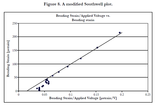
Figure 8. A modified Southwell plot.
The distribution of the strains (for the static case) at the beam’s root, (S.G. # 17 and 18) are described in Figures. 9a, 9b and 10, as a function of the applied voltage.Figure 9a presents the distribution of the strains at the clamped root of the beamas measured by strain gagesnumbers 17 & 18. One can clearly see a bifurcation point in the vicinity of the buckling voltage (around 1150 [V]) in which strain gage # 17 reverses its trend, while strain gage #18 continues it. To detect the buckling point, it is customed to both present the average compression strains and the average bending ones as a function of the applied voltage. This is done in Figure 9b, where noticeable bending strains are presented in the vicinity of the buckling voltage (again about 1150 [V]). Finally, the average bending strains are plotted as a function of the average compressions strains in Figure 10. A well-defined buckling voltage can be determined from Figure 10, yielding similar results to the ones presented in Figures 7 & 8. for the voltage which will induce buckling in the beam.
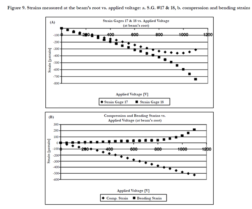
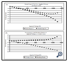
Figure 9. Strains measured at the beam’s root vs. applied voltage: a. S.G. #17 & 18, b. compression and bending strains.
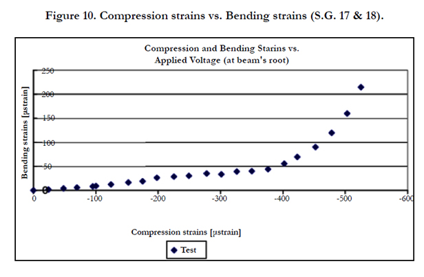
Figure 10. Compression strains vs. Bending strains (S.G. 17 & 18).
Discussion and Conclusions
A cantilever composite beam, with bonded piezoelectric patches,was buckled due to application of voltage on the patches. It was proved experimentally, that with the correct restrained ends of a beam, even for a cantilever beam, its natural frequencies can be altered and buckling can be reached, by only applying electrical voltage. Figures 11a-b try to explain schematically the phenomenon involved in the study. The resultant axial force at each cross section of the beam is zero for the cantilever beam. Two opposite components form this resultant: a resultant compressive force acting through the cross-sections centers of the beam and an equal tension force along the wire. When no lateral deflections are experienced by the beam the two components are collinear (Figure 11a), while in the presence of lateral deflections the two forces would yield a couple which is proportional to the magnitude of the two opposite components of the resultant axial force (Figure 11b). They are constant during the vibrations. When the magnitude of the lateral deflection (which varies harmonically) is large enough buckling can occur. The buckling of the beam was enabled due to the presence of a steel wire connecting its free end to the clamped side of the beam. The application of voltage to the six pairs of piezoelectric patches bean bonded on the surface of the beam’s profile induced tension stresses in the wire, thus causing the buckling of the beam due to the compressive stresses the beam was encountering.
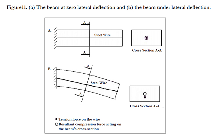
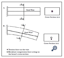
Figure11. (a) The beam at zero lateral deflection and (b) the beam under lateral deflection.
Acknowledgments
The author would like to thank Mr. A. Kotler for manufacturing the test specimen and for well performing the experimental campaign.
References
- Waisman H, Abramovich H (2002) “Variation of natural frequencies of beams using the active stiffening effect”. Composites Part B: Engineering 33(6): 415-424.
- Waisman H, Abramovich H (2002) “Active stiffening of laminated composite beams using piezoelectric actuators”. Composite Structures 58(1): 109-120.
- Ogauamanam D.C.D, Almeida S.F.M., Hansen J.S., (1998) “Stress stiffening effects in laminated beams with piezoelectric actuators”, J. Intell. Mater. Sys. Struct 9(2): 137-145.
- Hernande J.A., Almeida S.F.M., Nabarrete A. (2000) “Stiffening effects on the free vibration behavior of composite plates with PZT actuators”. Composite Structures 49(1): 55-63.
- de Faria A. R., Donadon M.V. (2010) “The use of piezoelectric stress stiffening to enhance buckling of laminated plates”. Latin American Journal of Solids and Structures Rio de Janeiro 7(2): 167-183.
- Kuo S.-Y. (2010) “Stiffening effects on the natural frequencies of laminated beams with piezoelectric actuators”. Journal of Aeronautics, Astronautics and Aviation, Series A 42(1): 67-72.
- Donadon M. V., Almeida S. F. M., de Faria A. R. (2002) “Stiffening effects on the natural frequencies of laminated plates with piezoelectric actuators”. Composites Part B: Engineering 33(5): 335-342.
- Wang Q., Quek S.T. (2002) “Enhancing flutter and buckling capacity of column by piezoelectric layers”. International Journal of Solids an Structures 39(16): 4167-4180.
- Thompson S. P., Loughlan J. (1995) “The active buckling control of some composite column strips using piezoelectric actuators”,Composite Structures 32(1-4): 59–67.
- M. Shariat M. (2009) “Dynamic buckling of imperfect laminated plates with piezoelectric sensors and actuators subjected to thermal-electromechanical loadings, considering the temperature-dependency of the material properties”. Composite Structures 88(2): 228–239.
- Fridman Y., Abramovich H (2008) “Enhancedstructural behavior of flexible laminated composite beams”. Composite Structures 82(1): 140-154.
- Meressi T., Paden B (1993) “Buckling control of a flexible beam using piezoelectric actuators”. Journal of Guidance, Control and Dynamics 16(5): 977-980.
- Mukherjee A., Joshi S.P., Ganguli A (2002) “Active vibration control of piezolaminated stiffened plates”. Composite Structures 55(4): 435–443.
- Abramovich H., Livshits A. (1993) "Dynamic behavior of cross-ply laminated beams with piezoelectric layers". Composite Structures 25(1-4): 371-379.
- Abramovich H, Livshits A. (1994) "Free vibrations of non-symmetric crossply laminated composite beams". J. of Sound and Vibration 176(5): 597-612.
- Abramovich H. (2011) "A new Insight on vibrations and buckling of a cantilevered beam under a constant piezoelectric actuation". Composite Structures 93(2): 1054–1057.
- Smart Material Corporation-www.smart-material.com
- ANSYS- www.ansys.com/products/
† Note that in Eqs. (2, 4b) one should use in the non-linear expression the term P rather than pm


