UAV Flight Dynamics
Philip Scott Blackwelder
Department of Mechanical and Aerospace Engineering, North Carolina State University, Raleigh, USA.
*Corresponding Author
Philip Scott Blackwelder,
Department of Mechanical and Aerospace Engineering,
North Carolina State University Raleigh, 27695, USA.
E-mail: psblackw@ncsu.edu
Received: November 11, 2015; Accepted: November 13, 2015; Published: December 21, 2015
Citation: Philip Scott Blackwelder (2015) UAV Flight Dynamics.Int J Aeronautics Aerospace Res. 2(6), 81-85.
doi: dx.doi.org/10.19070/2470-4415-150009
Copyright: Philip Scott Blackwelder© 2015 This is an open-access article distributed under the terms of the Creative Commons Attribution License, which permits unrestricted use, distribution and reproduction in any medium, provided the original author and source are credited.
Abstract
In the interest of promoting the integration of hybrid-electric power train into the aviation industry, research is being conducted by North Carolina State University to establish the feasibility of electrified power train in a small scale unmanned aerial vehicle (UAV). To accomplish this, it is first necessary to understand dynamics of the system to calculate the required power associated with each portions of the aircraft’s mission. Though research that has been conducted in the past based power required on published governing equations. However, in the interest of understand the system at its most fundamental level, it was deemed prudent to derive the governing equations from Newton’s second law.
Using analytical dynamics, a rotating coordinate system was applied to the craft and a rotation matrix was applied to establish the interaction of the aircraft’s external forces based on its Euler angles with respect to the inertial frame.
The equations associated with the values and interactions of the aircraft’s external forces were combined and manipulated to develop three governing parameters of maintaining flight during a typical UAV mission. These parameters are minimum airspeed, minimum power applied to the propeller, and the minimum roll angle required to accomplish a loitering maneuver with set radius about a target.
The next step of this research will be development of an optimization algorithm to match power train components to apply the necessary conditions derived in this paper.
2.Glossary of Variables
3.Introduction
4.Power Required to Maintain Flight
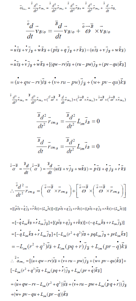
4.1.Derivation of Aircraft’s Acceleration Vector in the B Frame
4.2.External Forces Acting Upon the Aircraft
5.External Forces
5.1.Thrust Force
5.2.Lift Force
5.3.Drag Force
6.Conclusion
7.Acknowledgments
8.References
Keywords
Unmanned Ariel Vehicle; UAV; Flight Dynamics; Analytical Dynamics.
Glossary of Variables
ΚT – Thrust coefficient of the propeller
ρ – Air density
n – Rotational speed of the propeller (rev/s)
D – Propeller’s Diameter (in)
AP – Wing planform area
CL – Wing coefficient of lift
J – Propeller advance ratio (u/nD)
AF – Aircraft frontal area
CD – Sum of the parasitic (CDo) and lift induced (CDi) drag coefficients
AR – Wing aspect ratio
e – Oswald efficiency factor
Introduction
Though most associate unmanned aerial vehicles (UAVs) with the military, the number of nonmilitant applications is growing everyday including precision agriculture, package delivery, geological survey, and a myriad of other public applications. As such, it is becoming increasingly important for these vehicles to not only support longer mission durations but to also do so in a way that is cost effective and minimally pollutant both in emissions and noise. Given the current state of battery technology, purely electric UAVs fail to provide desirable mission durations. In addition, the noise and pollution associated with gasoline or other internal combustion engine powered UAVs is undesirable for applications in populated areas. Given these constraints, the best solution to achieve the desired goals of clean, quiet, and extended missions is to develop a hybrid-electric UAV platform. Hybrid-electric power train leverages the advantages of both energy sources while minimizing the disadvantages. This paper will outline the dynamics associated with a typical UAV missions and offer governing equations from which a hybrid-electric power train platform can be designed and optimized to offer peak efficiency while minimizing noise and emissions.
Power Required to Maintain Flight
Newton’s second law, the sum of the external forces on the aircraft is equal to the product of the craft’s mass and the acceleration of its center of mass with respect to the inertial frame (Figure 1).
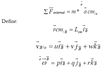
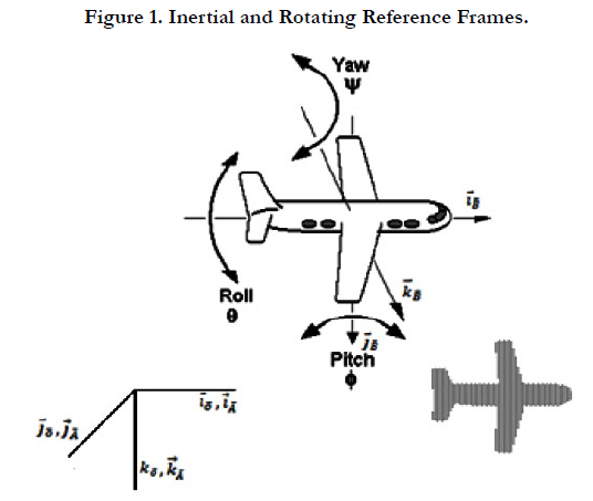
Figure 1. Inertial and Rotating Reference Frames.
From the free body diagram:
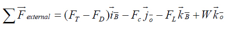
The term mgk→o‾ must be rotated into the B‾ frame; therefore a rotation matrix must be applied. The rotation about the inertial frame can be expressed with Euler angles. The vehicle will rotate Φ about i→o‾ , θ about j→o‾ , and ψ about k→o‾
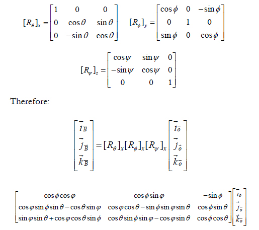
Therefore the forces in Equation 1 referencing the inertial frame can be expressed with respect to the aircraft’s frame:
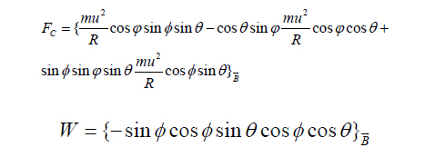
Assuming the angle φ = 0 at steady state, the sum of external forces then becomes:
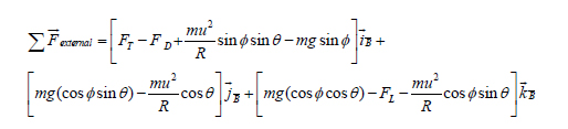
Setting the above equation equal to the expression found using Newton’s second law yields:
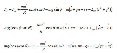
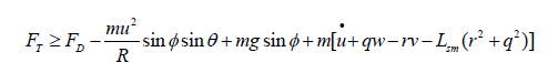
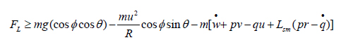
Therefore for the aircraft to maintain flight, the following must remain true:
The roll angle required to maintain equilibrium (assuming Φ=0) during loitering can also be derived from the sum of the forces about the j axis:
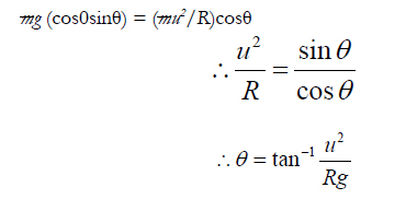
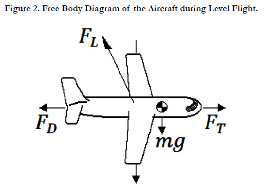
Figure 2. Free Body Diagram of the Aircraft during Level Flight.
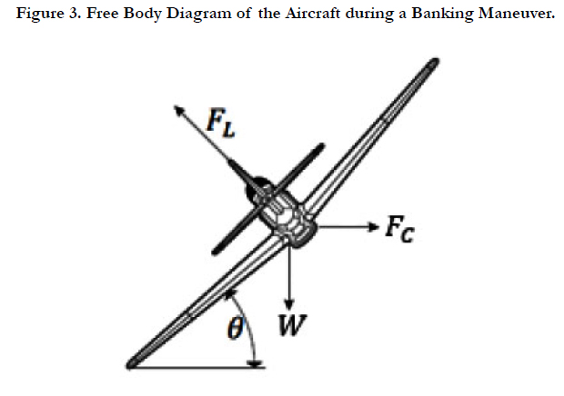
Figure 3. Free Body Diagram of the Aircraft during a Banking Maneuver.
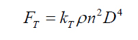
External Forces
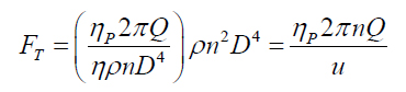
The thrust force (FT) is expressed as:
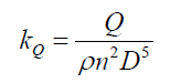
To establish the operating point of the engine to provide adequate thrust for maintaining flight, some relations can be applied using information about the propeller.
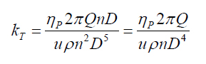
The propeller’s torque coefficient can be expressed as:
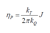
The torque coefficient can be related to the thrust coefficient through the propeller’s efficiency:
Rearranging Equation 7:
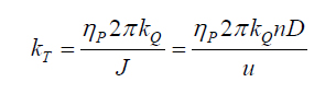
Plugging in Equation 6:
Plugging Equation 9 into Equation 5:
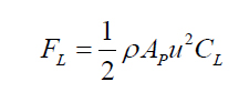
The lift force (FL) is expresses as:
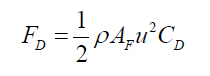
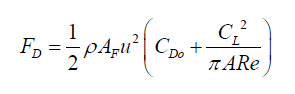
The total drag force (FD) is expressed as:
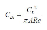
The coefficient of drag CD, is the sum of the coefficient of parasitic drag CD° and the lift induced drag coefficient. The lift induced drag coefficient is expressed as:
Therefore, the total drag is expressed as:
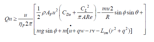
Plugging Equation 11 into Equation 2 and solving for Qn yields:
Plugging Equation 10 into Equation 3 yields:
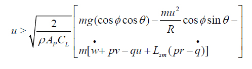
Equation 4, Equation 12, and Equation 13 serve as necessary conditions to sustain flight over the course of the mission. Equation 12 dictates the minimum combination of torque and shaft speed that must be delivered to the propeller, Equation 13 dictates the minimum speed that must be maintained to prevent stall, and Equation 4 dictates the minimum roll angle required to maintain a constant loitering radius about the target at the desired air speed.
Conclusion
The rapidly expanding market for UAVs will bring with it demand for more flexible platforms that can be quickly and easily assembled and modified based on mission parameters. Additionally, the increasing precedence of reducing fuel consumption and emissions is forcing designers to think more and more outside of the box to satisfy radically conflicting design requirements. Though adding additional complexity to an already sophisticated system can seem arduous, a firm understanding of the fundamental governing equations and the relationship between the various inputs and outputs, the design process becomes much more seamless.
Acknowledgments
I would like to thank Dr. Eric Klang for his patience and guidance over the ten years we have worked together at NC State University. I would also like to thank Dr. James Kribs for his selfless devotion to education in addition to facilitating and supervising all aerodynamic testing and for being my friend.
References
- Greitzer EM, Spakovszky ZS, Waitz IA (2015) Production of Thrust with a Propeller, Unified Propulsion. web.mit.edu/16.unified/www/SPRING/propulsion/UnifiedPropulsion7/UnifiedPropulsion7.htm
- Greitzer EM, Spakovszky ZS, Waitz IA (2015) Aircraft Performance, Unified Propulsion. ocw.mit.edu/ans7870/16/16.unified/propulsionS04/UnifiedPropulsion4/UnifiedPropulsion4.htm


