Finite Element Analysis and Vibration Testing of a Simple Replicate Beam-Type Aircraft Wing with and without Secondary Structure Attached
Santhosh K. N*, Yihun Y, Hamid M. L
Department of Mechanical Engineering, Wichita State University, Wichita, KS, USA.
*Corresponding Author
Santhosh K. Nedukanjirathingal,
Department of Mechanical Engineering,
Wichita State University, Wichita,
KS, USA.
E-mail: santhosh.k.nedukanjirathingal@spiritaero.com
Article Type: Research Article
Received: April 03, 2015; Accepted: May 18, 2015; Published: May 20, 2015
Citation: Santhosh K. N, Yihun Y, Hamid M. L (2015) Finite Element Analysis and Vibration Testing of a Simple Replicate Beam-Type Aircraft Wing with and without Secondary Structure Attached. Int J Aeronautics Aerospace Res. 2(3), 37-48. doi: dx.doi.org/10.19070/2470-4415-150005
Copyright: Santhosh K. N© 2015 This is an open-access article distributed under the terms of the Creative Commons Attribution License, which permits unrestricted use, distribution and reproduction in any medium, provided the original author and source are credited.
Abstract
Ground vibration testing (GVT) is one of the most critical testing procedures for an airplane certification. With proper GVT, analysts can determine the stiffness distribution, natural frequencies, mode shapes and structural damping of each airplane components which are needed for flutter analysis and dynamic loads analysis. Hence the results from GVT are highly important. The problem identified in this paper is one that misleads the structural designing and might result in catastrophic situations, if proper attention is not given to the GVT results. During GVT, technicians and engineers attempt to instrument most of the primary components of the airplane, totally avoiding secondary structures such as bungees, gears, control surfaces, etc. The secondary structures are also of equal importance as the primary structures so that analysts can identify the in-phase and out-of- phase modes. If not, the tuning of the stiffness of the primary structure might not be accurate for flutter analysis, especially when the in-phase and out-of-phase modes are near to the structural modes of the primary structure. The goal of this paper is to recreate the above mentioned problem of the in-phase and out-of-phase mode for a small wing-gear like structure. The detailed objectives and methodologies of the work include, simulating the modal experiments and finite element analysis (FEA) on a free-free beam (primary structure) with and without flexible links (secondary structure) attached to them, determining the stiffness distribution and modal characteristics of the primary structure and the secondary structures, using GVT and FEA. Characterizing the in-phase and out-of- phase modes which involves both primary and secondary structure by signal processing and using simplified beam model (stick model) is another important goal of this research.
2.Methodology
2.1 GVT of free-free beam without secondary structure
2.2 GVT of free-free beam with secondary structures
2.3 FEA of free-free beam without secondary structure
2.4 Stick model
2.5 FEA of free-free beam with flexible links (secondary structure)
3 Comparison of the Results
4.Conclusions
5.References
Introduction
The dynamic characteristics play an important role in flutter [1] and dynamic loads. For understanding and performing aeroelastic analysis and dynamic loads analysis, the primary input is the stiffness, the mass and inertia properties of each component. A GVT measures the modal characteristics of a structure [2] and is used in the process of structural modifications, flutter analysis etc. Simsiriwong and Sullivan [3] states that, one of the major methods to obtain the modal characteristics of an airplane structure is by the use of Frequency Response Functions (FRFs), which is nothing but a transfer functions in frequency domain. There are several suspension methods [4] which are used during the GVT of an airplane or its components, depending the size and weight of the structure. Generally used methods are suspension using bungee cords and suspending using an airbag system or multiple airbag systems. Mathew J. Whitney et al., [5] performed detailed analysis for suspension methods. Bungee cord is widely used and consists of strands of rubber which are wrapped in a woven sheath to form a cord. Research performed on the Global Hawk by Hensley et al., [6] uses airbags for simulating rigid body modes. Various input signals are used in this technique [7], multi sine, periodic chip, stepped sines, burst random etc. Vittala et al., [8] mentions about a full coarse FEM of an airplane for dynamic analysis. In this, they used CQUAD4 and CTRIA3 shell elements of MSC NASTRAN [9]. The total degrees of freedom of the model were 672000 and proper check was made to compare the total mass and center of gravity of the structure. Szkudlarek [4], modeled the hobby airplane using NASTRAN and it was discretized by using CBAR and CQUAD4 elements and the properties used were 2D PCOMP for composite materials and the CONM1 was used for lumped masses which are attached to the structure. Dennis Goge [16], in his research validates a finite element model of a four engine airplane with the test using the correlation analysis [19] and Modal Assurance Criterion. Salehi et al., [17], conducted a test and FEA on an airplane like structure. The FE model was constructed in ANSYS. The model was constructed by 32 beam elements. Hageman et al., [23] in their research, mentions about the dynamic effect of an un-modeled portion of a structure in a finite element model. The research concentrates on a method for including the dynamic behavior of the attached structure in a finite element model without modeling its precise geometry.
Two popular beam theories are:
a) Euler-Bernoulli beam theory and
b) Timoshenko beam theory.
The Euler- Bernoulli beam theory assumes that plane cross sections, normal to the neutral axis before deformation, continue to remain plane and normal to the neutral axis before deformation, continue to remain plane and normal. Shear deformation effects are negligible and hence valid for only slender beams. When the beams are thick, when shear- deformation effects are considered, Timoshenko beam theory comes in to use [10]. The bending vibration of a beam, is given by equation 1.1, where E, I, ρ and A are the young’s modulus, second moment of area of cross section, density, area of beam and L the length of the beam.
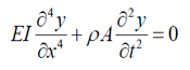
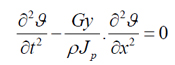
The change in angular orientation for the cross section of a beam is represented by equation 1.2 where, G is the shear modulus,ν is the poisson’s ratio, and is the torsional constant for a rectangular cross section and Jp is the polar moment of area of cross section.
Labonnote et al., [11] used an impact hammer to measure the damping of a wooden floor beam. Silva et al., [12] used FEM and test results to measure the modes and a comparison was made. Another such comparison on theoretical and software based comparison of cantilever beam are shown in the research paper written by Chaudhari et al., [13]. Azoury et al. describes the same kind of comparison between the experimental and FEM in their research [14]. Emory [15] and Sawant [16] in their research paper, mentions about the experimental verification of transverse vibrations of a free-free beam. Ali et al., [17] explains the use of an FFT analyzer in determining the modes of a cantilever beam and compared with the analytical results. Malekjafarian et al., [18] proposed methodologies for determining various rigid body modes from modal output data. To determine the rigid body modes, FRFs of the structure from different excitation points were obtained and all six rigid body modes cannot be detected in one FRF. Klopper et al., [19] proposed an experimental procedure that measures rigid body modes in approximately 1 min. Masoumi et al., [20] found out the inertia matrix from rigid body property estimation from FRFs. Schedlinski et al., [21] presented a procedure to identify rigid body properties of an elasto-mechanical system based on modal analysis. Marcos Arndt et al., [22] in their research mentioned about various commonly used FEM techniques in vibration analysis. h and p versions are the two refinement techniques they used. The first one consists of refinement of element mesh and the second one consists of using higher order shape functions in the element domain without any change in mesh.
This research performs a test of a free-free beam with and without a secondary structure attached to it. Bungee cords were used to hang the beam to simulate a non-constrained beam. Two finite elements were used for comparing the test data with the primary structure. The detailed model involved plate elements from NASTRAN and a simplified model with beam elements. In the first model, density card was used to incorporate the mass properties for the beam and in the beam model (stick model), lumped mass with proper inertias were used to analyze the natural frequencies and mode shapes. Secondary structure was modeled as a spring and mass system. FRFs were used to identify the modal characteristics. The primary objectives of this research is, to justify the importance of component GVT and importance of instrumenting secondary structures attached to the primary structures in full GVT of the assembled structure, to determine the modal characteristics of the beam with and without the flexible link attached. One of the other goal associated with this research is to verify whether a simple beam model can be used for structures involving secondary structures and how well the correlation with the tests can be performed.
Methodology
The goal of this research is to examine and quantify the effect of a secondary structure on a primary structure for a simple beam type replicate aircraft wing by experimental and finite element analysis. To achieve this goal, Vibration tests are initially conducted without the secondary structure attached to the primary structure and later tests are conducted with secondary structure attached to the primary structure. Doing so, the stiffness distributions of the primary structure are well determined before tuning the in-phase and out-of phase mode of the secondary structure. The steps involved to achieve the objectives are shown in Figure 1.
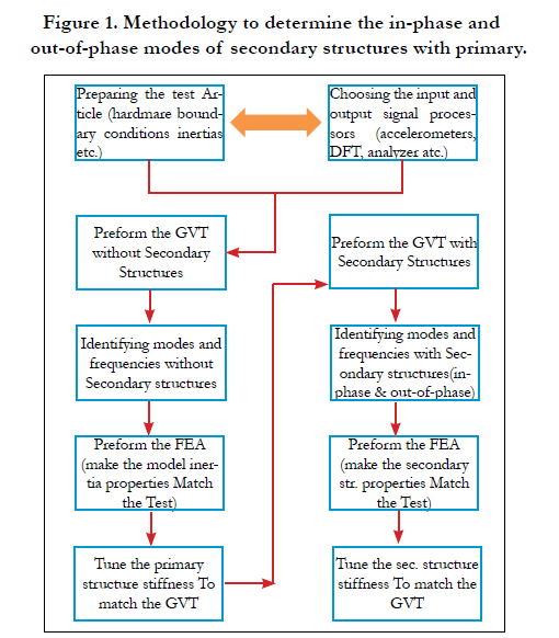
Figure 1. Methodology to determine the in-phase and out-of-phase modes of secondary structures with primary.
The GVT of the beam was performed by hanging the aluminum beam to a rigid structure using bungees as shown in Figure 2. The dimensions of the beam and the location of accelerometers are shown in Figure 3 and Figure 4 respectively. The cross section is hollow with outer width of 5.0”, height of 3.0” and thickness of 0.24”. The length of the beam is of 54.0”. The accelerometers used were uniaxial (Endevco 2222) and for force input an impact hammer (Dytran 5850B) was used. The signal processing tool used was Labview PXI-1000B.
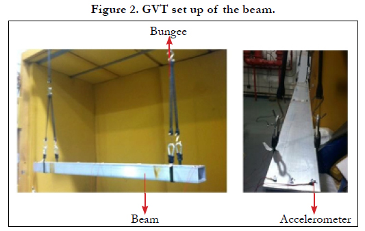
Figure 2. GVT set up of the beam.
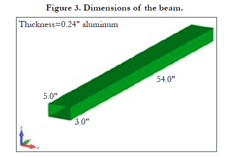
Figure 3. Dimensions of the beam.
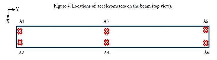
Figure 4. Locations of accelerometers on the beam (top view).
Figure 5 shows the magnitude and phase responses of accelerometers when applied force is near to A5. Figure 6 and shows the magnitude and phase responses of accelerometers when applied force is near to A6. The magnitude was measured in inches/(lb-sec2) and the phase in degrees.
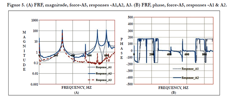
Figure 5. (A) FRF, magnitude, force-A5, responses-A1,A2, A3. (B) FRF, phase, force-A5, responses -A1 & A2.
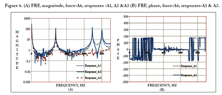
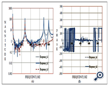
Figure 6. (A) FRF, magnitude, force-A6, responses -A1, A2 &A3 (B) FRF, phase, force-A6, responses-A1 & A2.
At 277 Hz, Figure 7, A1, A2, A5, and A6 are in phase, which shows that the mode at 277 Hz is a symmetric bending. At 694 Hz, Figure 8, the response from A1 and A2 are in-phase but the A1 & A2 responses are in out of phase with A5 & A6 respectively. This makes the mode anti-symmetric bending. Near 802 Hz, Figure 9, A1& A2 and A5 & A6 are out of phase, but A1 is in-phase with A6 and A2 is in phase with A5, which makes it a torsion mode. It is to be noted that Figure 5 (A) shows a small peak near 600 Hz. but, Figure 6 (A) doesn’t show a peak at 600 Hz. It was concluded that this peak is not a real global structural mode as the peaks are not there in both excitation from A5 and A6. At the same time the peak at 600 Hz is comparatively smaller than the other peaks.
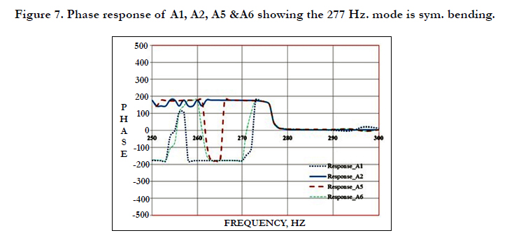

Figure 7. Phase response of A1, A2, A5 &A6 showing the 277 Hz. mode is sym. bending.
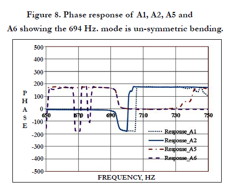
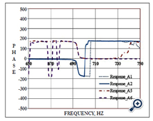
Figure 8. Phase response of A1, A2, A5 and A6 showing the 694 Hz. mode is un-symmetric bending.
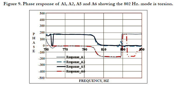
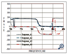
Figure 9. Phase response of A1, A2, A5 and A6 showing the 802 Hz. mode is torsion.
Figure 10 shows the test setup of the beam with links with 0.6 lb attached 16.0” from each ends of the beam. Accelerometers A7 and A8 are attached to the link in fore-aft direction (direction 1) as shown. It can be seen that from Figure 11, at 75 Hz A7 and A8 are out-of phase and at 113 Hz they are in-phase. From Figure 12, it is evident that the other peaks on the beam are at 273 Hz, 686 Hz and 784 Hz.
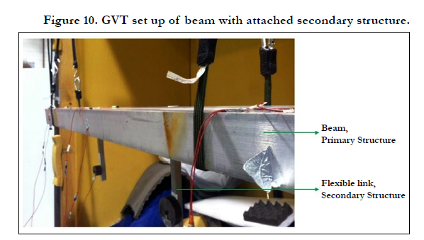
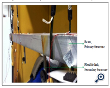
Figure 10. GVT set up of beam with attached secondary structure.
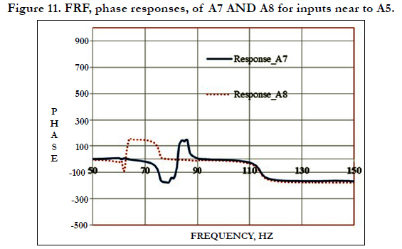
Figure 11. FRF, phase responses, of A7 AND A8 for inputs near to A5.
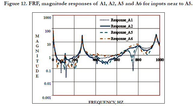
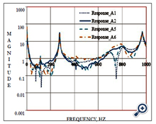
Figure 12. FRF, magnitude responses of A1, A2, A5 and A6 for inputs near to A5.
To identify the characteristics of those modes, Figure 13 shows that at 273 Hz all the accelerometers are in phase which shows it as symmetric bending mode. Figure 14 (A) shows that A1& A2 are in-phase and A5 & A6 are in- phase but A1 is in out-of-phase with A5, which shows the mode as anti-symmetric bending mode. Figure 14 (B) shows that A1 & A2 are out-of-phase, same as A5 and A6; while A1 and A6 are in-phase which shows the mode as a torsion mode.
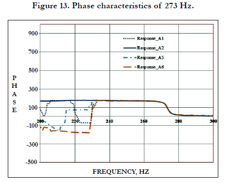
Figure 13. Phase characteristics of 273 Hz.
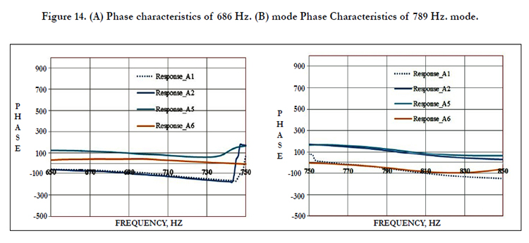
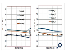
Figure 14. (A) Phase characteristics of 686 Hz. (B) mode Phase Characteristics of 789 Hz. mode.
A finite element modal analysis was performed on the beam. The bungees were represented by spring element represented in Figure. 15. The model was build using FEMAP and the solver used was MSC NASTRAN. CQUAD elements were used, for the model, with thickness of 0.24”. 1296 QUAD elements and 1322 grid points were used in the model. The material properties used were of aluminum, which is E, young’s modulus of 1.0E7 psi, shear modulus of 3.8 E6 psi and poison’s ratio of 0.3. The spring stiffness used for representing bungees, are of relatively low values to represent the rigid body modes of frequencies close to 1 HZ, which is much lower value than the first structural mode. Nastran Sol 103 was performed on the model and the natural frequencies were extracted to match up with the test results. The mode shapes of all those natural frequencies are shown in Figure 16-17.
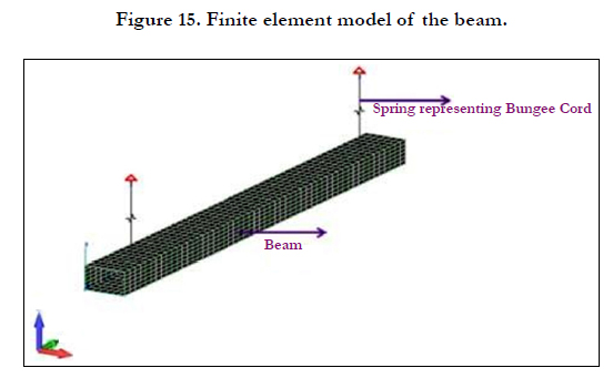
Figure 15. Finite element model of the beam.
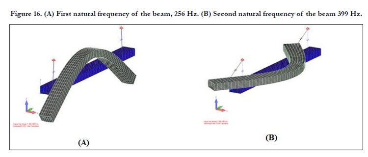
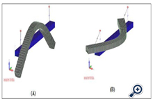
Figure 16. (A) First natural frequency of the beam, 256 Hz. (B) Second natural frequency of the beam 399 Hz.
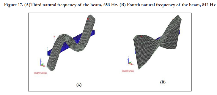
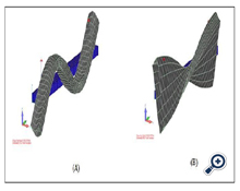
Figure 17. (A)Third natural frequency of the beam, 653 Hz. (B) Fourth natural frequency of the beam, 842 Hz
A ‘stick model’ was developed, where the whole hollow beam can be represented by equivalent beam elements. To develop this simplified model, the detailed coarse model was divided into separate bays, equidistant, where the shear center of the cross section was connected to the various points in structure by RBE3, as shown in Figure 18. A moment of 100 lb-in was applied at one end and the other end was constrained in three dof (x, y and z). From the output file, the rotational displacements were measured to determine the section properties, EI1, EI2 and GJ. For the given Young’s modulus and shear modulus, the section properties of the cross section, I1, I2 and J can be determined. I1 mostly determines the vertical bending frequency, I2 determines the fore-aft frequency and J contributes to the torsional frequency.
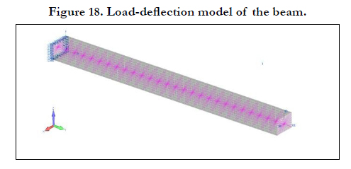
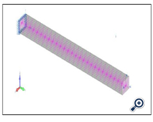
Figure 18. Load-deflection model of the beam.
The simplified ‘stick model’ of the beam is shown in Figure 19. The Stiffness distribution of the beam from the above methodology is shown in Figure 20. Using the previously mentioned methodology, the section modulus were determined to be, I1=3.9 in4, I2=9.8 in4 and J=8.3 in4.
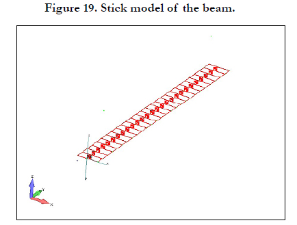
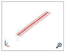
Figure 19. Stick model of the beam.
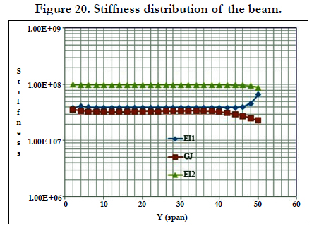
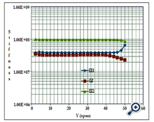
Figure 20. Stiffness distribution of the beam.
The modal comparison of the stick model was also performed. Figure 21-22 shows the mode shapes and frequencies associated with each mode on the stick model.
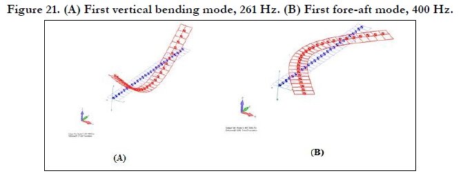
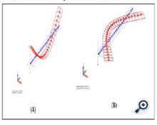
Figure 21. (A) First vertical bending mode, 261 Hz. (B) First fore-aft mode, 400 Hz.
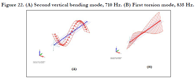
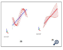
Figure 22. (A) Second vertical bending mode, 710 Hz. (B) First torsion mode, 835 Hz.
A comparison on the transfer function between the test, coarse FEM and stick models were also performed, shown in Figure. 23. Nastran Sol 111 was used to determine the FRF from FEA.
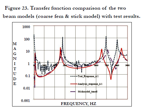
Figure 23. Transfer function comparison of the two beam models (coarse fem & stick model) with test results.
Modal analysis of the free-free beam with flexible links was performed using the stick model. The flexible links were modeled as rigid elements with a spring and mass attached to the primary structure, which makes it flexible. The spring stiffness was ‘tuned’ to match up with the test results and dof which the spring stiffness was made flexible is the rotational direction 5. Figure 24 shows the beam model (stick model) and the two links attached to the beam.
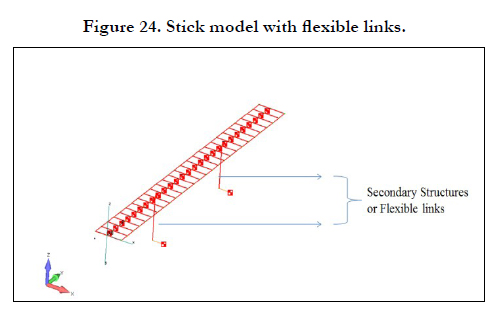
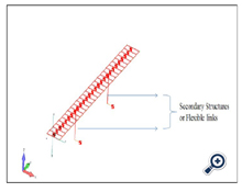
Figure 24. Stick model with flexible links.
The link structure frequencies are lower than the structural frequency of the beam. The natural frequencies of the system are the ‘peaks’ in Figure 25 (A). Figure 25 (B) shows that at 73 Hz, the links are out of phase (anti- symmetric) with each other and at 113 Hz. they are in-phase (symmetric). Figure 26-28 shows the mode shapes of the rest of the structural frequencies. A comparison of transfer function on A1 and A7 are shown in Figure 29 and 30, respectively.
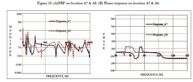
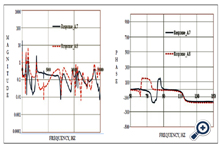
Figure 25. (A)FRF on location A7 & A8. (B) Phase response on location A7 & A8.
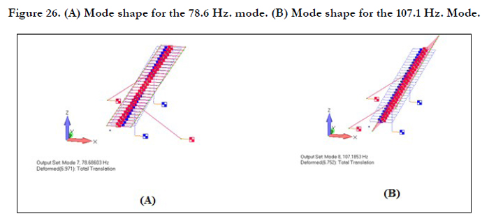
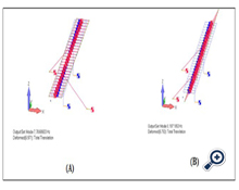
Figure 26. (A) Mode shape for the 78.6 Hz. mode. (B) Mode shape for the 107.1 Hz. Mode.

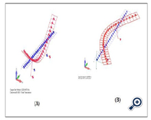
Figure 27. (A)Bending mode, 253.4 Hz. (B) Fore-aft mode, 406 Hz.
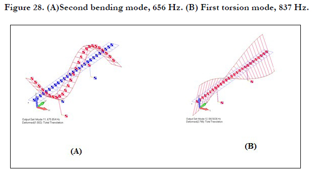
Figure 28. (A)Second bending mode, 656 Hz. (B) First torsion mode, 837 Hz.
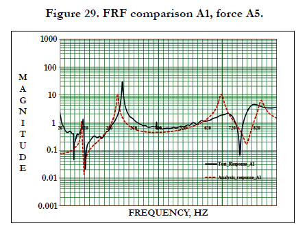
Figure 29. FRF comparison A1, force A5.
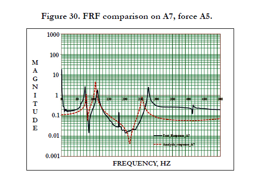
Figure 30. FRF comparison on A7, force A5.
Comparison of the Results
The comparison of the frequencies and mode shapes was performed with and without the secondary structure attached to the primary structure, beam. Table 1 shows the comparison of the free-free beam modal test results with respect to the two finite element analysis (FEA) results. One of the FEA used the coarse mesh model and the other used the ‘stick model’. Table 2 shows the comparison of the FEA results using the stick model with the flexible links incorporated into the model with respect to the test results. Figure 23 shows the FRF comparison of the test results with the two finite element models (coarse mesh and stick model), without the secondary structure attached to the primary structure. The 1st symmetric bending mode shows a difference of 5.78% and the rest of the real modes show very low differences. Figure 29 and 30 shows the FRF comparison for the model with the secondary structure attached. The links out-of phase mode shows a difference of 7.67 % and the symmetric bending mode shows a difference of 7.18%.
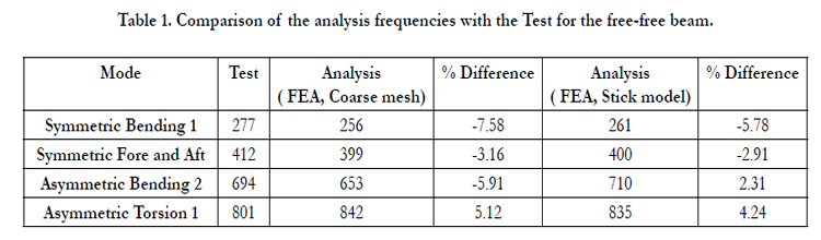

Table 1. Comparison of the analysis frequencies with the Test for the free-free beam.
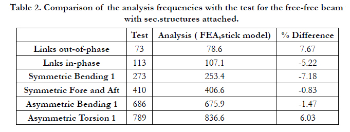
Table 2. Comparison of the analysis frequencies with the test for the free-free beam with sec.structures attached.
Conclusions
The goal of this study was to examine and quantify the effect of secondary structure on primary structure in terms of frequencies and modes for a simple beam type replicate of an aircraft wing. With the addition of the secondary structure mass, the frequency of the primary structure reduces. Demonstrated the importance of a primary structure component GVT by itself and the importance of instrumenting secondary structures during ‘full GVT’. One of the easiest ways to differentiate the primary structure modes coupled with secondary structures is to perform a component GVT of primary structure by itself and account for the stiffness and mass properties of the primary structure. An experimental methodology to determine the basic first order natural frequencies of the free-free beam was successfully performed. The results were compared to the finite element analysis. Magnitude and phase responses from the test were carefully analyzed to differentiate the bending modes (Symmetric and anti-symmetric) and torsion modes (both symmetric and anti-symmetric). Natural frequencies and modes of flexible links attached to free-free beam were analyzed on the basis of test data. Careful analysis and interpretation of the FRFs were performed to determine the in-phase and out-of-phase modes of the secondary structure (flexible ink) with the primary structure using FEA. A comparison of the test results and the two FEA methodologies were performed. The FEA results were well correlated with the test and are within a reasonably good agreement. Here the simple stick FE model can be utilized in the correlation process for the GVT of a real wing. It is proved that any parametric study to be performed on the model, analysts can use the simplified stick model. For the GVT of the free-free beam with secondary structures, characterization of the in-phase and out-of phase modes of the secondary structures were also analyzed along with the correlation with FEA. If the modal test was performed on the assembled structure without instrumenting the secondary structure, analysts would see two peaks of torsional frequencies, if the secondary structure mode is near the vicinity of the real torsion mode, one in-phase torsion mode with flexible links and the other out-of-phase mode. If the analysts don’t have the knowledge of the in-phase and out-of-phase mode of the secondary structure to the primary, there is high possibility that the tuning of the stiffness could happen in two ways, one which results in lower frequency (in-phase) and the other higher (out-ofphase). If the stiffness of the primary structure was tuned to the in-phase torsion mode from the test, that will be very conservative approach from a flutter analysis perspective, which might result in increasing the stiffness by changing the cross section and probably result in increasing the weight of an aero-structure. Instead, if the primary structure stiffness was tuned to the out-of-phase torsion mode, which will be a very non-conservative approach for flutter, affects the safety, of the structure. Hence to avoid both the weight impact and improve the safety, proper testing, i.e., instrumenting the secondary structure is essential along with the component GVT of the primary structure by itself.
References
- Kurniawan, R., (2013) “Numerical study of flutter of two dimensional aeroelastic system,” WCE 2013, London, U.K.
- Kehoe, W.M., and Freudinger, L. C, (1993) “Aircraft Ground Vibration Testing at NASA Dryden Flight Research Facility,” NASA Technical Memorandum.
- Simsiriwong, J., and Sullivan, W., (2008) “Vibration Testing of a Carbon Composite Fuselage,” American Society for Composites 23rd Technical Conference, TN, US.
- Szkudlarek, W., Mizutani, A., Peeters, B., Luczak, M., and Kahsin, M., (2009) “Ground Vibration Testing, Finite Element Modeling and Correlation of a Composite Hobby Aircraft,” 13th Aerospace Sciences and Aviation Technology, Cairo, Egypt.
- Whitney, J.M., Panza, L.J., and Brillhart, D.R., “GVT Suspension Effects on Correlation of the Predator B vehicle,” IMAC XX.
- Hensley, D., Smith, K., Doane, B., and Dreyer, W., Orlando,F (1997) “Implementation of an airbag suspension system for the global hawk vibration test,” IMAC XV.
- Peeters, B., Hendricx, W., Debille, J. and Climent, H. (2008) “Modern Solutions for Ground Vibration Testing of Large Aircraft,” IMAC, Orlando, FL.
- Vittala, N.G.V, Pankaj, A.C., and Swarnalatha, R., (2008) ”Dynamic and Aeroelastic Analysis of a Transport Aircraft,” proceedings of the International Conference on Aerospace science and Technology, Bangalore, India.
- MSC/NASTRAN (2014) Quick Reference Guide.
- Malatkar, P.,, (2003) Doctor of Philosophy Dissertation, “Nonlinear Vibrations of Cantilever Beams and Plates,” Virginia Polytechnic Institute and State University, Virginia.
- Labonnote, N., Malo, A.K., (2011) “Damping Measurements in Timber Beams Using Impact Testing,”8th International Conference on Structural Dynamics , EURODYN, Belgium.
- Haro, L., Santade, F., Goncalves P., Sousa, E., (2014) “Dynamic Analysis for Different Finite Element Models of Beams with Viscoelastic Damping Layer,” International Conference on Structural Dynamics ,EURODYN, Portugal.
- Chaudhari,K.P, Patel, D., and, Pael, V., (2014) “Theoretical and Software based comparison of cantilever beam Modal Analysis,” IJIRAE.
- Azoury C., Kallassy,A., Combes, B., Moukarzel, I., and Boudet, R., (2012) “Experimental and analytical Modal Analysis of a Crankshaft,” ISOR Journal of Engg.
- Emory, H.B., and Zhu, W. D., (2006) “Experimental Modal Analysis of Rectangular and Circular Beams,” Journal of STEM Education.
- Sawant, S. H., (2013) “Experimental Verification of Transverse Vibration of Free-Free beam,” International Journal of Advanced Research in Electrical Electronics and iInstrumentation Engineering.
- Mohammad Vaziri, M., Ali Vaziri, A., Kadam, S.S., (2013) “Vibration analysis of a cantilever beam using F.F.T analyzer,” International Journal of Advanced Engineering Technology.
- Malekjafarian, A., Ashory, R.M.,Khatibi, N.M., Latibari, M.S.,, “A new method for estimation of rigid body properties from output-only modal data,” International Operational Modal Analysis Conference, IOMAC’11.
- Klopper,R., Akita,H., Okuma, M., and Terada, S., “An experimental Identification method for rigid body properties enabled by gravity dependent suspension modelling,” 1St Joint International Conference on Multibody System Dynamics, Finland.
- Masoumi, M., Shahbazmohamadi, S., Ashory, M.R “Sensitivity Analysis of Rigid body property estimation from modal method,” IMAC XXV111,Florida.
- Schedlinski, C. and Link, M., (1997) “On the identification of rigid body properties of an elastic system,” IMAC, FL.
- Machado, M.A., and, Scremin, A., (2010) “An adaptive generalized finite element method applied to free vibration analysis of straight bars and trusses,” Journal of sound and vibrations.
- Hageman, D., and Ford, D. (1997),”Expimentally characterized dynamic structures in an analytical finite element solution,” IMAC XV - 15th International Modal Analysis Conference.


